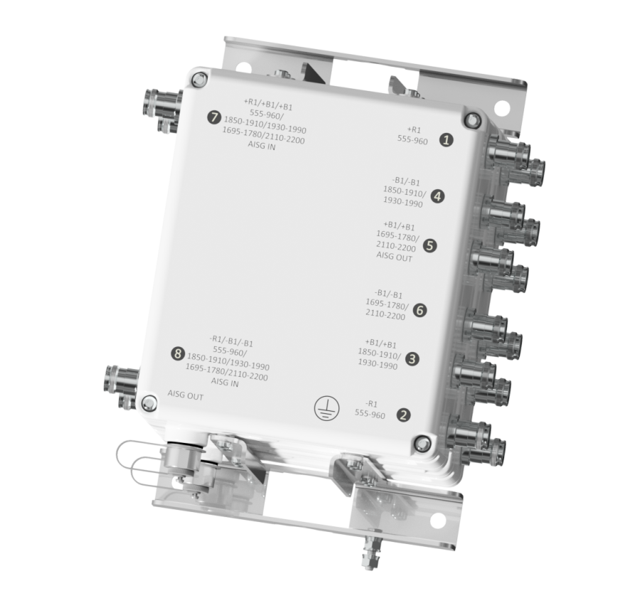
TWIN TMA 1900/AWS/LOWPASS 555-960MHz 6 ANT
NON-DIPLEXED 1900/AWS ANTENNA PORTS
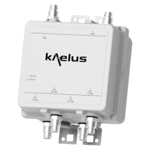
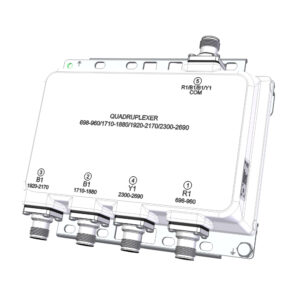
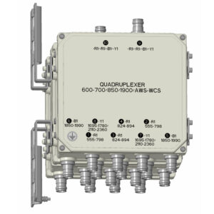
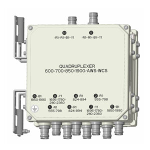
Designed to be deployed in co-located AWS & 1900 networks, the Kaelus TMA2124 provides gain in 1900 and AWS uplink, using independent LNAs per band and per channel. Low loss bypass 555-960MHz signal to low band antennas is also provided.
FEATURES
- Improved base station sensitivity through excellent noise figure performance and linearity
- AISG 2.0 compatible, full software upgradable using AISG “personality” upload
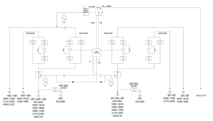
- DC/AISG passthrough to AWS antenna (port 5)
- AISG OUT connector disabled when AISG device (SBT equipped antenna) present on Port 3 +R1/+R1
- One AISG subunit per LNA, 4 in total. All fixed gain
- 555-960 bypass to low band antenna
Electrical block diagram
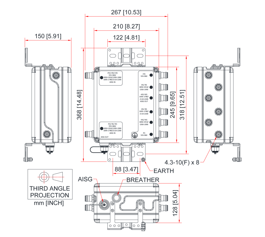
Mechanical block diagram
Technical specifications |
|||||||||||||||
| Band Name | 1900 | AWS | |||||||||||||
| downlink | |||||||||||||||
| Passband | 1930 – 1990MHz | 2110 – 2200MHz | |||||||||||||
| Insertion loss | 0.4dB typical | 0.3dB typical | |||||||||||||
| Return loss | 22dB typical | ||||||||||||||
| Maximum input power | 160W (average) / 2kW (PEP) | 160W (average) / 2kW (PEP) | |||||||||||||
| Intermodulation products | -155dBc maximum, at antenna port in RX band with 2 x 20W carriers | -163dBc maximum, at antenna port in RX band with 2 x 20W carriers | |||||||||||||
Uplink |
|||||||||||||||
| Passband | 1850 – 1910MHz | 1695 – 1780MHz | |||||||||||||
| Gain | 13dB | ||||||||||||||
| Gain variation | ±1dB maximum | ||||||||||||||
| Return loss | 22dB typical | ||||||||||||||
| Bypass return loss | 14dB typical | ||||||||||||||
| Bypass loss | 3dB typical | ||||||||||||||
| Noise figure | 1.2dB typical @ 13dB gain | 1.0dB typical @ 13dB gain | |||||||||||||
| Output IP3 | +28dBm typical | ||||||||||||||
| Maximum input power with no damage | +12dBm | ||||||||||||||
555-960 lowpass filter |
|||||||||||||||
| Passband | 555 – 960MHz | ||||||||||||||
| Insertion loss | 0.2dB typical | ||||||||||||||
| Return loss | 21dB typical | ||||||||||||||
| Maximum input power | 250W (average) / 2.5kW (PEP) | ||||||||||||||
| Intermodulation products | -155dBc maximum, at antenna port with 2 x 20W carriers | ||||||||||||||
| electrical | |||||||||||||||
| Impedance | 50Ohms | ||||||||||||||
| Power supply and alarm (current window alarm mode, default) | |||||||||||||||
| Current window alarm mode (CWA) is the default operating mode and can be configured to specific customer requirements. The TMA2124F03V4 is configured so that both channels are independently powered and monitored via their respective BTS port, 7 or 8. The BTS port sinks additional current to indicate an alarm state in its uplink path. Normal operating and alarm current values are configured independently via a field-loadable personality file. Please contact Kaelus for more information. | |||||||||||||||
| DC supply voltage | +8.5 to +18V DC, case is DC ground | ||||||||||||||
| DC supply | Each BTS port powered individually | ||||||||||||||
| DC supply current, normal mode | 200mA per port typical (both ports are powered) | ||||||||||||||
| DC supply current, alarm mode | 300mA per port typical (both ports are powered) | ||||||||||||||
| Aisg mode of operation (auto selected on valid aisg 2.0 frames) | |||||||||||||||
| AISG signals can be applied to port 7 or port 8. The TMA unit switches to AISG mode when valid frames are detected on either port 7 or 8. All LNAs take DC power from the port with the AISG frames or, if DC is present on both ports, power will be supplied equally between the ports. Each LNA is controlled uniquely by its sub-unit number. | |||||||||||||||
| DC supply voltage | +7.5V to +30V DC | ||||||||||||||
| AISG version | 2.0 (1.1 optional) | ||||||||||||||
| Supply current, AISG mode | 500mA @ 7.5V, 135mA @ 30V typical | ||||||||||||||
| AISG connector, current rating | IEC60130-9, 8-pin female, < 4A peak, 2A continuous, pin 6 | ||||||||||||||
| Field firmware upgradable | Yes (R951022ATA2.0 Rev 2.9.12) | ||||||||||||||
| AISG pass through to antenna port | Yes | ||||||||||||||
| Antenna aisg ook + dc | |||||||||||||||
| When DC is applied it is quickly switched through to port 5. If an over-current condition is detected, DC & AISG are disconnected from port 5. If DC remains connected to the load at port 5, DC and AISG are disconnected from the AISG OUT 8 pin connector. If DC is disconnected from port 5, DC and AISG are enabled at the AISG OUT 8 pin connector. If a short circuit is detected at the AISG OUT 8 pin connector, DC and AISG are disabled. | |||||||||||||||
| Mode of Operation | Voltage at Port 5 |
Assumption | “Autosense + Protection” Switch Status |
Comment | |||||||||||
| AISG or CWA | High | Device present or open circuit |
Close | DC & AISG OOK will be supplied to port 5. DC & AISG is removed from the AISG OUT 8 pin port |
|||||||||||
| AISG or CWA | Low | DC short circuit or low DC resistance |
Open | DC & AISG OOK will not be supplied to port 5. DC & AISG are supplied to the AISG OUT 8 pin port |
|||||||||||
Environmental |
|||||||||||||||
| For further details of environmental compliance, please contact Kaelus. | |||||||||||||||
| Temperature range | -40ºC to +65ºC | -40°F to +149°F | ||||||||||||||
| Ingress protection | IP67 | ||||||||||||||
| Altitude | 3,000m | 10,000ft | ||||||||||||||
| Lightning protection | IEC61312-1, RF: ±5kA maximum (8/20us), AISG: ±2kA maximum (8/20us) | ||||||||||||||
| MTBF | >1,000,000 hours | ||||||||||||||
| Compliance | FCC Part 15 subpart B | ||||||||||||||
| mechanical | |||||||||||||||
| Dimensions H x D x W | 245 x 128 x 210mm | 9.65 x 5.04 x 8.27in Excluding connectors | ||||||||||||||
| Weight | 8.1kg | 17.86lbs | ||||||||||||||
| Finish | Painted, light grey (RAL 7035) | ||||||||||||||
| Connectors | 4.3-10 (F) x 8 long neck, AISG (F) x 1 | ||||||||||||||
| Wind Load | Front 390N, Side 147N (Single) Front 251N, Side 409N (Twin) At 74m/s (AS/NZS 1170-2-2011 Structural design – Wind actions – Cyclone areas) |
||||||||||||||
| Mounting | Pole/wall bracket supplied with two metal clamps 45-178mm diameter poles | ||||||||||||||
Ordering information |
|||||||||||||||
| Part Number | Configuration | Optional Features | Connectors | ||||||||||||
| TMA2124F03V5-1D | TWIN 2 in / 6 out | STANDARD | 4.3-10 (F) | ||||||||||||
| TMA2124F03V5-2D | QUAD 4 in / 12 out | STANDARD | 4.3-10 (F) | ||||||||||||
| TMA2124F03V5-1S | TWIN 2 in / 6 out | STANDARD | 4.3-10 (F) | ||||||||||||
| TMA2124F03V5-2S | QUAD 4 in / 12 out | STANDARD | 4.3-10 (F) | ||||||||||||