TMA TWIN 800/900
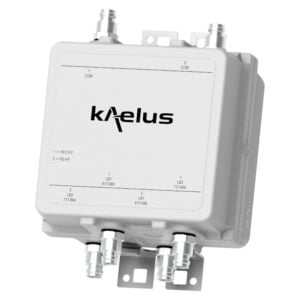
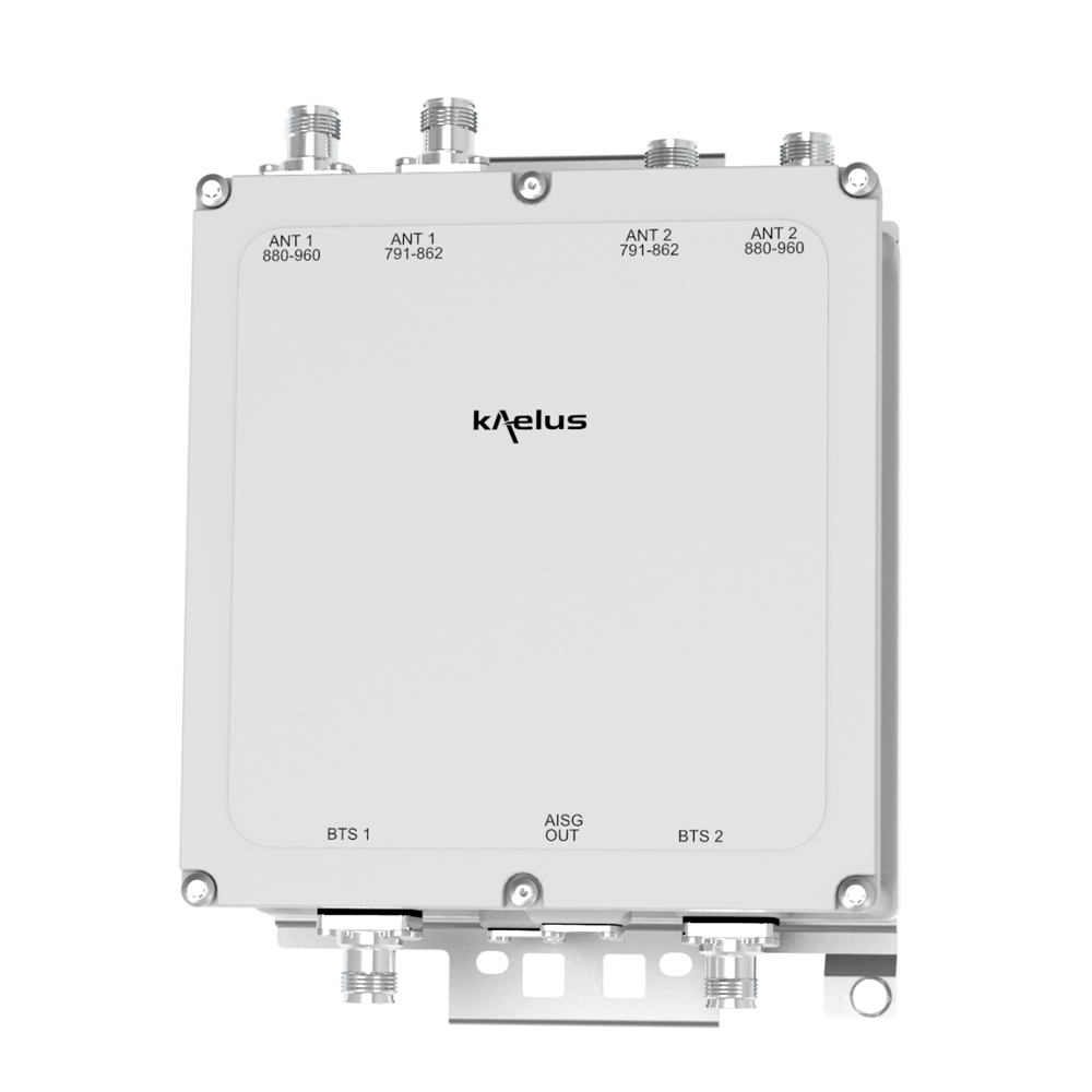
Designed to be deployed in collocated 800 and 900 systems, the Kaelus MI-165 enhances cell uplink coverage in 800 and 900 through improved system noise figure, thereby saving operational and capital expenditure.
FEATURES
- Improved base station sensitivity through gain in the 800 and 900 uplink
- 4 Antenna ports
- Excellent noise figure performance
- Full AISG operation and RET antenna support, AISG2.0 compatible
- Small and light for minimum visual impact
TECHNICAL SPECIFICATIONS |
|||||||||||||||
| BAND NAME | 800 | 900 | |||||||||||||
| DOWNLINK | |||||||||||||||
| Passband | 791 – 821MHz | 925 – 960MHz | |||||||||||||
| Insertion loss | 0.4dB typical | 0.4dB typical | |||||||||||||
| Return loss | 18dB minimum | ||||||||||||||
| Maximum input power | 200W (average) | 200W (average) | |||||||||||||
| Intermodulation products | -159dBc in RX band at ANT | ||||||||||||||
| UPLINK | |||||||||||||||
| Passband | 832 – 862MHz | 880 – 915MHz | |||||||||||||
| Gain | 12dB nominal | ||||||||||||||
| Return loss | 16dB minimum | ||||||||||||||
| Bypass return loss | 12dB minimum | ||||||||||||||
| Bypass loss | 1.7dB maximum | ||||||||||||||
| Noise figure | 1.1dB typical | ||||||||||||||
| Output IP3 | 25dBm typical | ||||||||||||||
| ELECTRICAL | |||||||||||||||
| Impedance | 50Ohms | ||||||||||||||
| POWER SUPPLY AND ALARM (CURRENT WINDOW ALARM MODE, DEFAULT) | |||||||||||||||
| Current window alarm mode (CWA) is the default operating mode and can be configured to specific customer requirements. Please contact Kaelus for more information. | |||||||||||||||
| DC supply voltage | +9 to +15V DC | ||||||||||||||
| DC supply current, normal mode | 165mA @ 12V | ||||||||||||||
| DC supply current, alarm mode | 320mA max | ||||||||||||||
| AISG MODE OF OPERATION (AUTO SELECTED ON VALID AISG 2.0 FRAMES) | |||||||||||||||
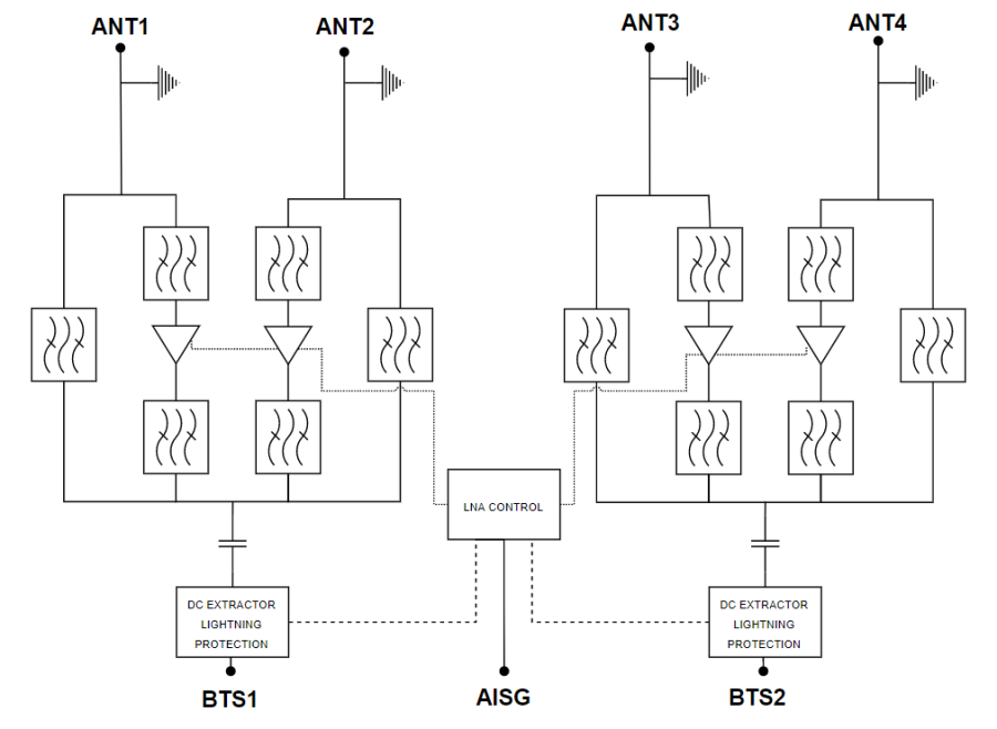
| AISG signals can be applied to the BTS ports. The TMA unit switches to AISG mode when valid frames are detected on either port. Each LNA is controlled uniquely by its sub-unit number. | |||||||||||||||
| DC supply voltage | 24 V DC nominal (+9.0V to +31V DC) | ||||||||||||||
| AISG version | 1.1 or 2.0 | ||||||||||||||
| Power consumption, AISG mode | < 4W | ||||||||||||||
| AISG connector, current rating | IEC60130-9, 8-pin female, 1.6A | ||||||||||||||
| ENVIRONMENTAL | |||||||||||||||
| For further details of environmental compliance, please contact Kaelus. | |||||||||||||||
| Temperature range | -40ºC to +65ºC | -40°F to +149°F | ||||||||||||||
| Ingress protection | IP67 | ||||||||||||||
| Lightning protection | IEC61312-1, RF: ±10kA (8/20us), AISG: ±5kA (8/20us) | ||||||||||||||
| MTBF | >1,000,000 hours | ||||||||||||||
| Compliance | EMC: EN 301 489-8 Safety: EN 62368-1 Operation: ETSI EN 300 019-1-4 class 4.1E Storage: ETS 300 019-1-1 class 1.2 |
||||||||||||||
| MECHANICAL | |||||||||||||||
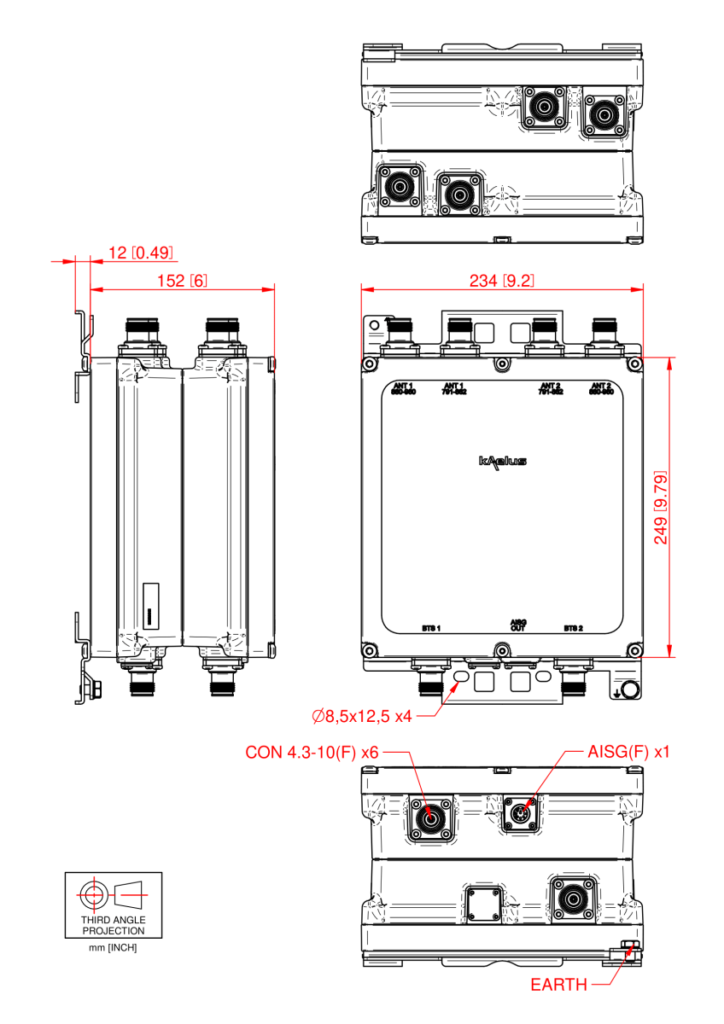
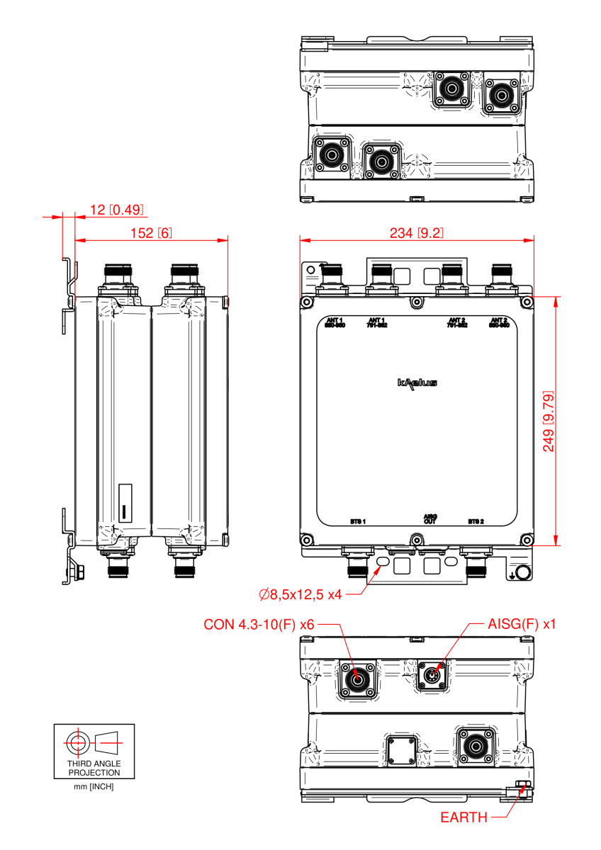
| Dimensions H x D x W | 249 x 152 x 234 mm | 9.8 x 6 x 9.2in (excluding brackets and connectors) | ||||||||||||||
| Weight | 9.5kg | 20.94lbs | ||||||||||||||
| Finish | Powder coated, NCS 1502-R | ||||||||||||||
| Connectors | See ordering information | ||||||||||||||
| Mounting | Pole/wall bracket using two metal clamps, suits 40-140mm diameter poles | ||||||||||||||
ORDERING INFORMATION |
|||||||||||||||
| PART NUMBER | CONFIGURATION | OPTIONAL FEATURES | CONNECTORS | AISG MODE | |||||||||||
| MI-16501 | TWIN, 2 in / 4 out | BASE MODEL | 7/16 (F) 1xAISG |
COMMON MODE ONETWO (*) |
|||||||||||
| MI-16502 | TWIN, 2 in / 4 out | BASE MODEL | 7/16 (F) 1xAISG |
COMMON MODE TWOTWO (**) |
|||||||||||
| MI-16506 | TWIN, 2 in / 4 out | BASE MODEL | 7/16 (F) 2xAISG |
INDEPENDENT | |||||||||||
| MI-16531 | TWIN, 2 in / 4 out | BASE MODEL | 4.3-10 (F) 1xAISG |
COMMON MODE ONETWO (*) |
|||||||||||
| MI-16532 | TWIN, 2 in / 4 out | BASE MODEL | 4.3-10 (F) 1xAISG |
COMMON MODE TWOTWO (**) |
|||||||||||
| MI-16536 | TWIN, 2 in / 4 out | BASE MODEL | 4.3-10 (F) 2xAISG |
INDEPENDENT | |||||||||||
| (*) ONETWO: the TMA is identified as 1 logic unit with 2 subunits | |||||||||||||||
| (**) TWOTWO: the TMA is identified as 2 logic units with 2 subunits each | |||||||||||||||
ELECTRICAL BLOCK DIAGRAM |
MECHANICAL BLOCK DIAGRAM |