TMA TWIN 1800/2100 WITH L-BAND BYPASS
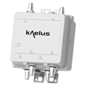
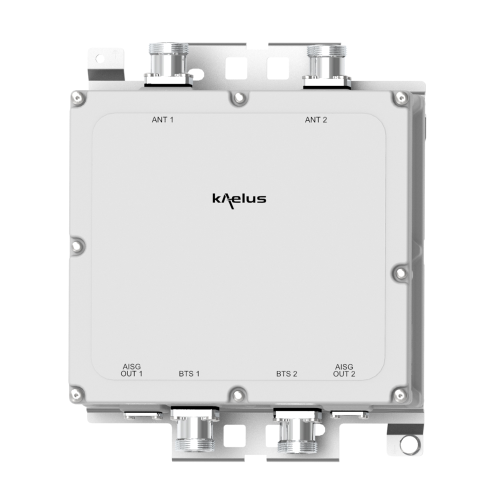
Designed to be deployed in collocated L-Band, 1800 and 2100 systems, the Kaelus MI-183 enhances cell uplink coverage in 1800, 2100 through improved system noise figure, thereby saving operational and capital expenditure.
FEATURES
- Improved base station sensitivity through gain in the 1800 and 2100 uplink
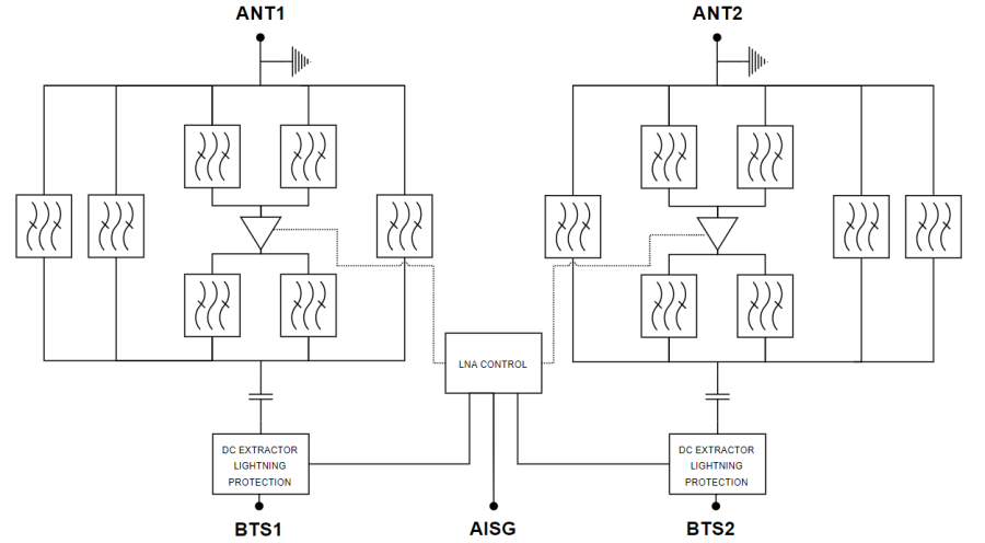
- Internal diplexing on the antenna port of L-Band, 1800 and 2100 bands: 2 Antenna ports
- Excellent noise figure performance
- Full AISG operation and RET antenna support, AISG2.0 compatible
- Small and light for minimum visual impact
TECHNICAL SPECIFICATIONS |
|||||||||||||||
| BAND NAME | 1800 | 2100 | |||||||||||||
| DOWNLINK | |||||||||||||||
| Passband | 1805 – 1880MHz | 2110 – 2170MHz | |||||||||||||
| Insertion loss | 0.5dB typical | 0.3dB typical | |||||||||||||
| Return loss | 18dB minimum | ||||||||||||||
| Maximum input power | 200W (average)(*) | 200W (average)(*) | |||||||||||||
| Intermodulation products | -160dBc in RX band at ANT | -168dBc in RX band at ANT | |||||||||||||
| UPLINK | |||||||||||||||
| Passband | 1710 – 1785MHz | 1920 – 1980MHz | |||||||||||||
| Gain | 12dB nominal | ||||||||||||||
| Return loss | 16dB minimum | ||||||||||||||
| Bypass loss | 2dB typical | ||||||||||||||
| Noise figure | 1.4dB typical | 1.3dB typical | |||||||||||||
| Output IP3 | 25dBm typical | ||||||||||||||
| Maximum input power with no damage | 12dB typical | ||||||||||||||
| L-BAND BYPASS PATH | |||||||||||||||
| Passband | 1427 – 1496MHz | ||||||||||||||
| Return loss | 18dB minimum | ||||||||||||||
| Insertion loss | 0.25dB typical | ||||||||||||||
| Maximum input power with no damage | 200W (average)(*) | ||||||||||||||
| (*) For models with 4.3-10 connector, limited to 500W (average) combined power at the common port. |
| ELECTRICAL | |||||||||||||||
| Impedance | 50Ohms | ||||||||||||||
| POWER SUPPLY AND ALARM (CURRENT WINDOW ALARM MODE, DEFAULT) | |||||||||||||||
| Current window alarm mode (CWA) is the default operating mode and can be configured to specific customer requirements. Please contact Kaelus for more information. | |||||||||||||||
| DC supply voltage | +9 to +15V DC | ||||||||||||||
| DC supply current, normal mode | 165mA @ 12V | ||||||||||||||
| DC supply current, alarm mode | 320mA max | ||||||||||||||
| AISG MODE OF OPERATION (AUTO SELECTED ON VALID AISG 2.0 FRAMES) | |||||||||||||||
| AISG signals can be applied to the BTS ports. The TMA unit switches to AISG mode when valid frames are detected on either port. | |||||||||||||||
| DC supply voltage | +9.0V to +31V DC | ||||||||||||||
| AISG version | 1.1 or 2.0 | ||||||||||||||
| Power consumption, AISG mode | < 4W | ||||||||||||||
| AISG connector, current rating | IEC60130-9, 8-pin female, 1.6A | ||||||||||||||
| ENVIRONMENTAL | |||||||||||||||
| For further details of environmental compliance, please contact Kaelus. | |||||||||||||||
| Temperature range | -40ºC to +65ºC | -40°F to +149°F | ||||||||||||||
| Ingress protection | IP67 | ||||||||||||||
| Lightning protection | RF: ±5kA (8/20us), AISG: ±2.5kA (8/20us) common mode | ||||||||||||||
| MTBF | >1,000,000 hours | ||||||||||||||
| Compliance | EMC: EN 301 489-8 Safety: IEC/EN 62368-1 Operation: ETSI EN 300 019-1-4 class 4.1E Storage: ETS 300 019-1-1 class 1.2 |
||||||||||||||
| MECHANICAL | |||||||||||||||
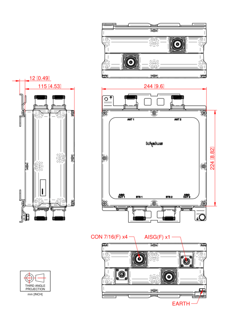
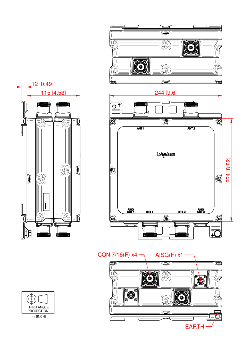
| Dimensions H x D x W | 224 x 115 x 244 mm | 8.8 x 4.5 x 9.61in (excluding brackets and connectors) | ||||||||||||||
| Weight | 8kg | 17.6lbs | ||||||||||||||
| Finish | Powder coated, NCS 1502-R | ||||||||||||||
| Connectors | See ordering information | ||||||||||||||
| Mounting | Pole/wall bracket using two metal clamps, suits 40-140mm diameter poles | ||||||||||||||
| SHIPPING INFORMATION | |||||||||||||||
| Carton size | 360 x 260 x 180mm │ 14.7 x 10.24 x 7.09in | ||||||||||||||
| Gross weight (including packaging) | 9kg │ 20lb | ||||||||||||||
ORDERING INFORMATION |
|||||||||||||||
| PART NUMBER | CONFIGURATION | OPTIONAL FEATURES | CONNECTORS | AISG MODE | |||||||||||
| MI-18301 | TWIN, 2 in / 2 out | BASE MODEL | 7/16 (F) 1xAISG |
COMMON MODE ONETWO (*) |
|||||||||||
| MI-18302 | TWIN, 2 in / 2 out | BASE MODEL | 7/16 (F) 1xAISG |
COMMON MODE TWOTWO (**) |
|||||||||||
| MI-18306 | TWIN, 2 in / 2 out | BASE MODEL | 7/16 (F) 2xAISG |
INDEPENDENT | |||||||||||
| MI-18331 | TWIN, 2 in / 2 out | BASE MODEL | 4.3-10 (F) 1xAISG |
COMMON MODE ONETWO (*) |
|||||||||||
| MI-18332 | TWIN, 2 in / 2 out | BASE MODEL | 4.3-10 (F) 1xAISG |
COMMON MODE TWOTWO (**) |
|||||||||||
| MI-18336 | TWIN, 2 in / 2 out | BASE MODEL | 4.3-10 (F) 2xAISG |
INDEPENDENT | |||||||||||
| (*) ONETWO: the TMA is identified as 1 logic unit with 2 subunits each | |||||||||||||||
| (**) TWOTWO: the TMA is identified as 2 logic units with 2 subunits each | |||||||||||||||
ELECTRICAL BLOCK DIAGRAM |
MECHANICAL BLOCK DIAGRAM |