TWIN SAME BAND COMBINER
CDMA850 A’/B’ + LTE700/LTE850 A/B-BANDS
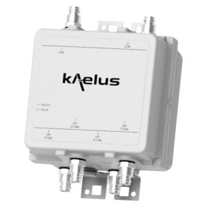
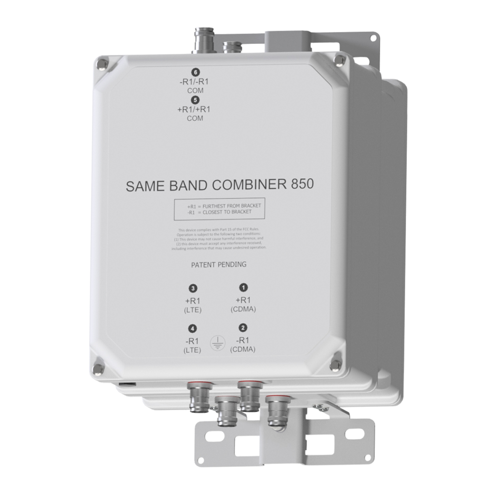
Designed to combine LTE700/LTE850 radio(s) with legacy CDMA850 equipment, the Kaelus DBC0134 is a low loss twin combiner with excellent insertion loss and passive inter-modulation performance.
FEATURES
- Combines/splits legacy CDMA850 & LTE700H/LTE850 A/B-bands
- Supports 10MHz LTE expansion in 850MHz A and/or B-bands
- Allows LTE700/LTE850 & CDMA routing to separate antennas
- Ideal for use with dual band LTE700 & LTE850 radios
- Supports CDMA channels placed in either A’ or B’
- Extremely close (zero guardband) spacing
- Designed for low passive inter-modulation
- DC/AISG autosensing with LED status
- Low insertion loss
TECHNICAL SPECIFICATIONS |
|||||||||||||||
| BAND NAME | R1 (CDMA) | R1 (LTE) | |||||||||||||
| Passband | A’ (CH691), B’ (CH738/CH779 or CH770) | LTE700, LTE850 (746-844.5, 869-889.5MHz) | |||||||||||||
| Insertion loss | 1.1dB typical, 1.9dB maximum | 746-798MHz: 0.45dB typical, 0.55dB maximum 824-844.5, 869-889.5MHz: 1.0dB typical, 1.9dB maximum |
|||||||||||||
| Return loss | 24dB typical, 20dB minimum | 24dB typical, 20dB minimum | |||||||||||||
| EVM | 3% typical, 7% maximum | 0.5% typical, 2% maximum | |||||||||||||
| Group delay variation | 250ns maximum | 270ns maximum | |||||||||||||
| Absolute group delay | 120ns typical (mid-band 350ns maximum (band-edge) |
75ns typical (mid-band) 300ns maximum (band-edge) |
|||||||||||||
| Maximum input power | 80W (average) / 800W (PEP) | 160W (average) / 1600W (PEP) | |||||||||||||
| ISOLATION COM PORT MUST BE TERMINATED IN 50OHMS | |||||||||||||||
| CDMA 850 TX frequency range |
35dB typical, 30dB minimum | ||||||||||||||
| LTE 850 TX frequency range |
35dB typical, 30dB minimum | ||||||||||||||
| CDMA 850 RX frequency range |
35dB typical, 30dB minimum | ||||||||||||||
| LTE 850 RX frequency range |
35dB typical, 30dB minimum | ||||||||||||||
| 746-806MHz | 33dB typical, 28dB minimum | ||||||||||||||
| ELECTRICAL | |||||||||||||||
| Impedance | 50Ohms | ||||||||||||||
| Intermodulation products | -160dBc typical / -155dBc maximum all ports with 2 x 20W carriers (out of band IM testing <3 minutes) | ||||||||||||||
| DC / AISG | |||||||||||||||
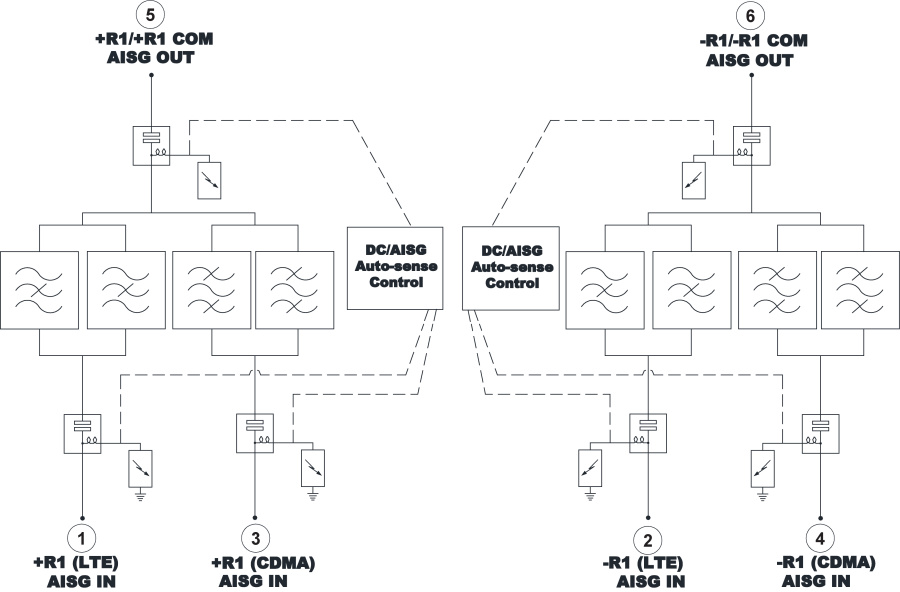
| The DC/AISG path is automatically selected. In bottom of the tower applications (combiner mode), each RF channel port is sequentially checked for the presence of DC voltage. If more than one port has voltage, the port that has the highest (programmed) priority is passed to the common port. If a short circuit is detected on the common port DC/AISG is disabled. In top-of-tower applications (splitter mode), DC/AISG is passed to all ports that do not present a short circuit. If a short circuit is detected, the shorted RF port will be disabled for DC/AISG while other RF ports remain connected. | |||||||||||||||
| Input voltage range | 8 – 30V DC | ||||||||||||||
| DC current rating | 2.0A continuous, 2.5A maximum | ||||||||||||||
| Compliance | 3GPP, TS 37.461 | ||||||||||||||
| Current consumption | 5mA typical, 10mA maximum | ||||||||||||||
| Port priority (combiner mode) | R1 (LTE) first, R1 (CDMA) second | ||||||||||||||
| ENVIRONMENTAL | |||||||||||||||
| For further details of environmental compliance, please contact Kaelus. | |||||||||||||||
| Temperature range | -20ºC to +65ºC | +4°F to +149°F | ||||||||||||||
| Ingress protection | IP67 | ||||||||||||||
| Altitude | 3,000m | 10,000ft maximum | ||||||||||||||
| Lightning protection | RF: ±5kA maximum (8/20us) | ||||||||||||||
| MTBF | >1,000,000 hours | ||||||||||||||
| Compliance | ETSI EN 300 019-1-4 class 4.1, RoHS | ||||||||||||||
| MECHANICAL | |||||||||||||||
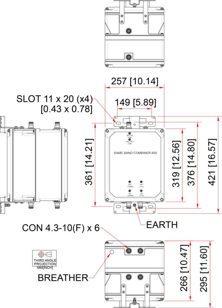
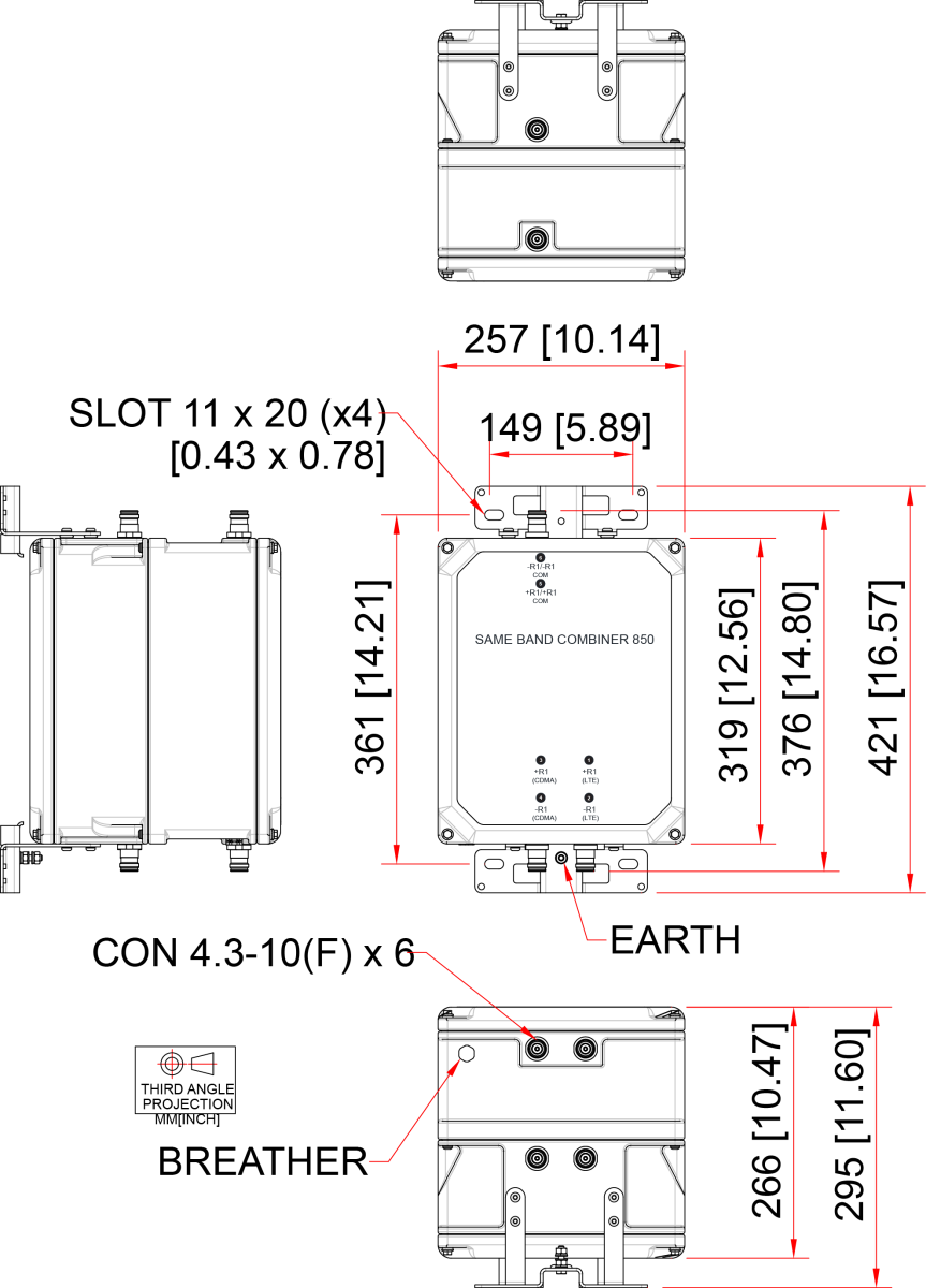
| Dimensions H x D x W | 319 x 257 x 266mm | 12.56 x 10.13 x 10.47in | ||||||||||||||
| Weight | 20.5kg | 45.1lbs | ||||||||||||||
| Finish | Painted, light grey (RAL7035) | ||||||||||||||
| Connectors | 4.3/10 (F) x 6 long neck | ||||||||||||||
| Mounting | Pole/wall bracket supplied with two metal clamps for 45-178 mm diameter poles | ||||||||||||||
ORDERING INFORMATION |
|||||||||||||||
| PART NUMBER | R1 (CDMA) | R1 (LTE) | DESCRIPTION | ||||||||||||
| DBC0134F1V72-1 | A’ (CH691), B’ (CH738/CH779 or CH770) | LTE700, LTE850 (746-844.5, 869-889.5MHz) | Twin SBC, 700, 850 DC AUTO R1 (LTE) |
||||||||||||
ELECTRICAL BLOCK DIAGRAM |
MECHANICAL BLOCK DIAGRAM |