TWIN SAME BAND COMBINER 850
B-BAND
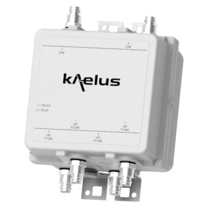
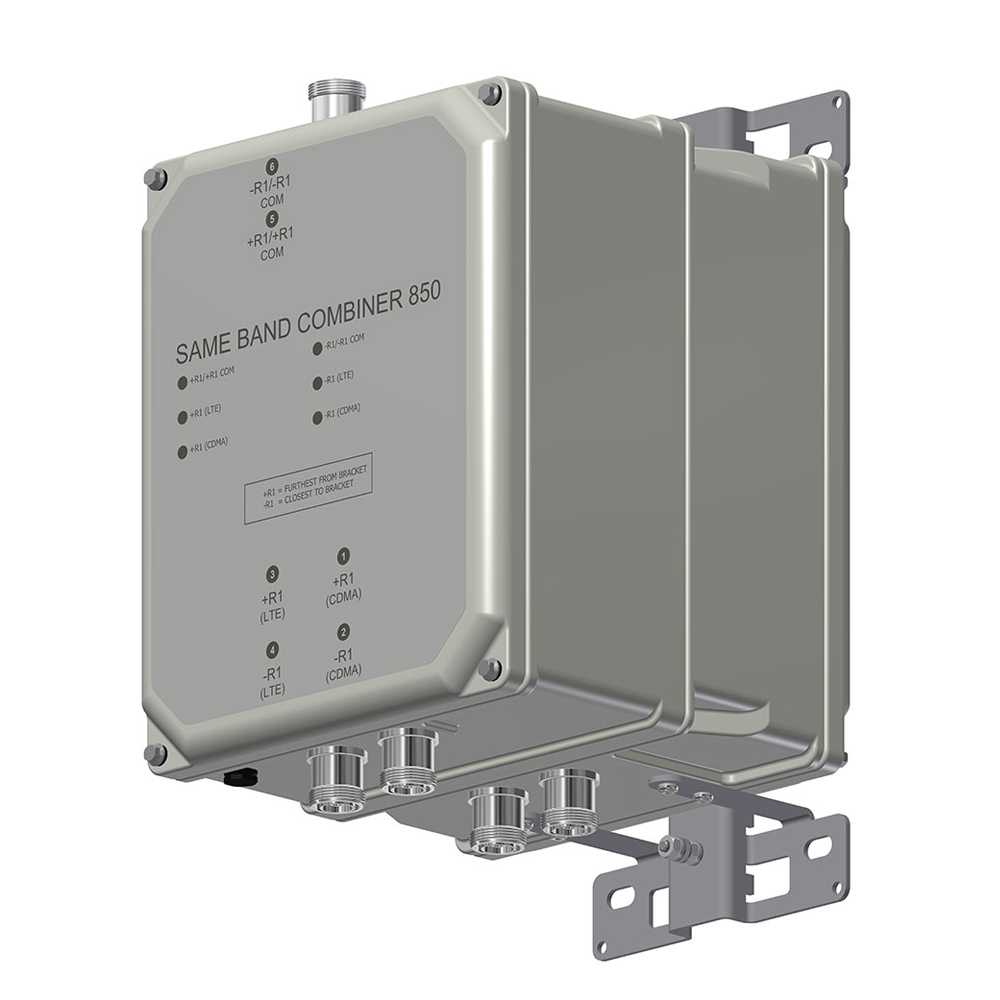
Designed to combine two 850MHz base stations within Band 5 B-band, the Kaelus DBC0111 provides a low loss combiner with excellent insertion loss and passive inter-modulation performance.
FEATURES
- Combines legacy CDMA with single 5MHz LTE carrier
- Extremely close (zero guardband) spacing
- Designed for low passive inter-modulation
- DC/AISG autosensing
- Low insertion loss
TECHNICAL SPECIFICATIONS |
|||||||||||||||
| BAND NAME | R1 (CDMA) | R1 (LTE) | |||||||||||||
| Passband | CH384, 425, 466 & 770 | EARFCN 2585 | |||||||||||||
| Insertion loss | 1.0dB typical | 1.1dB typical | |||||||||||||
| EVM | 2% typical, 7% maximum | 0.5% typical, 2% maximum | |||||||||||||
| Group delay variation | 270ns maximum | 250ns maximum | |||||||||||||
| Absolute group delay | 300ns maximum (band-edge) 33ns typical (mid-band) |
350ns maximum (band-edge) 75ns typical (mid-band) |
|||||||||||||
| ISOLATION COM PORT MUST BE TERMINATED IN 50OHMS | |||||||||||||||
| R1 (CDMA) TX frequency range |
35dB typical, 30dB minimum | ||||||||||||||
| R1 (LTE) TX frequency range |
35dB typical, 30dB minimum | ||||||||||||||
| R1 (CDMA) RX frequency range |
35dB typical, 30dB minimum | ||||||||||||||
| R1 (LTE) RX frequency range |
35dB typical, 30dB minimum | ||||||||||||||
| ELECTRICAL | |||||||||||||||
| Impedance | 50Ohms | ||||||||||||||
| Return loss | 20dB minimum, 24dB typical. | ||||||||||||||
| Intermodulation products | -153dBc maximum all ports with 2 x 20W carriers (out of band IM testing <3 minutes) | ||||||||||||||
| Maximum input power | CDMA Channel:160W (average) / 1.6kW (PEP) LTE Channel:80W (average) / 800W (PEP) |
||||||||||||||
| DC / AISG | |||||||||||||||
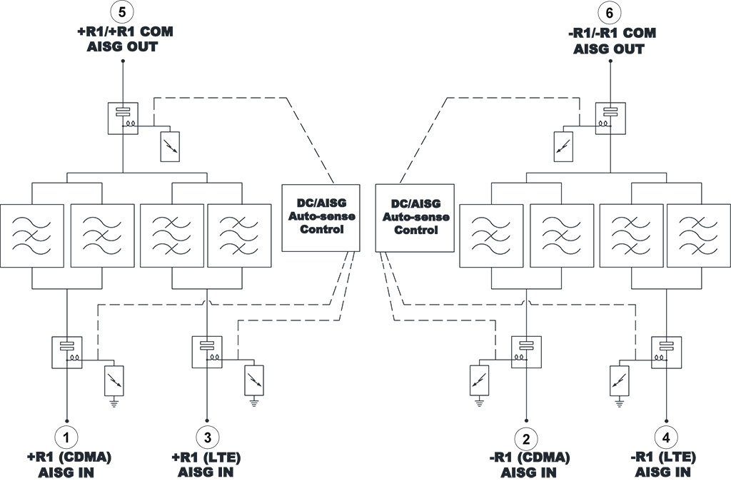
| The DC/AISG path is automatically selected. In bottom of the tower applications (combiner mode), each RF channel port is sequentially checked for the presence of DC voltage. If more than one port has voltage, the port that has the highest (programmed) priority is passed to the common port. If a short circuit is detected on the common port DC/AISG is disabled. In top-of-tower applications (splitter mode), DC/AISG is passed to all ports that do not present a short circuit. If a short circuit is detected, the shorted RF port will be disabled for DC/AISG while other RF ports remain connected. To reduce current consumption at low supply voltage, LEDs are sequentially enabled. | |||||||||||||||
| Input voltage range | 7.5 – 30V DC | ||||||||||||||
| DC current rating | 2.5A continuous | ||||||||||||||
| Compliance | 3GPP, TS 25.461 | ||||||||||||||
| Current consumption | 15mA typical, 25mA maximum | ||||||||||||||
| Port priority (combiner mode) | R1 (LTE) first, R1 (CDMA) second | ||||||||||||||
| LEDs | 1 bi-colour LED per RF port connector | ||||||||||||||
| LEDs, bottom of tower application: | |||||||||||||||
| – DC/AISG not present | Off | ||||||||||||||
| – DC/AISG pass | Green | ||||||||||||||
| – DC/AISG present, not passed | Red | ||||||||||||||
| LEDs, top of tower application: | |||||||||||||||
| – DC/AISG pass | Green | ||||||||||||||
| – All ports disabled | COM LED red | ||||||||||||||
| ENVIRONMENTAL | |||||||||||||||
| For further details of environmental compliance, please contact Kaelus. | |||||||||||||||
| Temperature range | -20ºC to +65ºC | +4°F to +149°F | ||||||||||||||
| Ingress protection | IP67 | ||||||||||||||
| Altitude | 3,000m | 10,000ft maximum | ||||||||||||||
| Lightning protection | RF: ±5kA maximum (8/20us) | ||||||||||||||
| MTBF | >1,000,000 hours | ||||||||||||||
| Compliance | ETSI EN 300 019 class 4.1, RoHS | ||||||||||||||
| MECHANICAL | |||||||||||||||
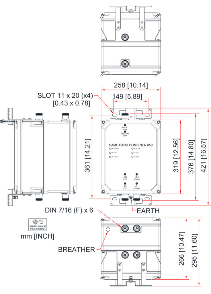
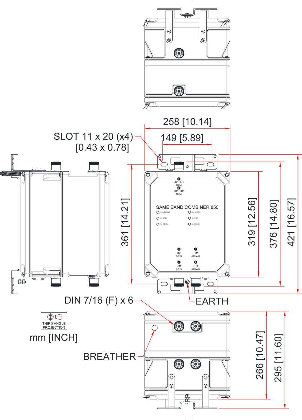
| Dimensions H x D x W | 319 x 257 x 266mm | 12.56 x 10.13 x 10.47in | ||||||||||||||
| Weight | 20.9kg | 46.1lbs | ||||||||||||||
| Finish | Painted, light grey (RAL7035) | ||||||||||||||
| Connectors | DIN 7-16 (F) x 6 long neck | ||||||||||||||
| Wind Load | Front 426N, Side 468N At 74m/s (AS/NZS 1170-2-2011 Structural design – Wind actions – Cyclone areas) |
||||||||||||||
| Mounting | Pole/wall bracket supplied with two metal clamps for 45-178 mm diameter poles | ||||||||||||||
ORDERING INFORMATION |
|||||||||||||||
| PART NUMBER | R1 (CDMA) | R1 (LTE) | DESCRIPTION | ||||||||||||
| DBC0111F2V62-1 | CH 384, 425, 466, 770 | EARFCN 2585 | Twin SBC, B-band DC AUTO R1 (LTE) |
||||||||||||
ELECTRICAL BLOCK DIAGRAM |
|||||||||||||||
MECHANICAL BLOCK DIAGRAM |