DIPLEXER 700/850-900
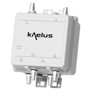
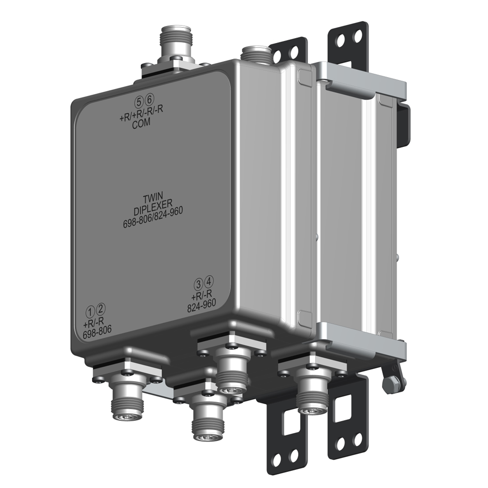
The Kaelus DBC0157 is a bi-directional diplexer designed to combine 700 and 850-900 technologies. The DBC0157 provides low insertion loss and excellent passive intermodulation performance. The DBC0157 can be used at either the BTS or antenna end of the feeder.
FEATURES
- Enables antenna/feeder sharing for 700 and 850-900 networks
- Low insertion loss & high return loss
- Low passive IM performance
- Multiple DC/AISG bypass configurations available with built-in lightning protection
- Single and twin models available
TECHNICAL SPECIFICATIONS |
|||||||||||||||
| PORT NAME | 700 | 850-900 | |||||||||||||
| Passband | 698 – 806MHz | 824 – 960MHz | |||||||||||||
| Insertion loss | 0.35dB typical | ||||||||||||||
| Return loss | 18dB minimum | ||||||||||||||
| Maximum input power | 250W (average) | 250W (average) | |||||||||||||
| Intermodulation products | -160 dBc maximum with 2 x +43dBm TX Carrier | ||||||||||||||
| Isolation in 700 band | N/A | 50dB minimum | |||||||||||||
| Isolation in 850-900 band | 50dB minimum | N/A | |||||||||||||
| ELECTRICAL | |||||||||||||||
| Impedance | 50Ohms | ||||||||||||||
| DC / AISG | |||||||||||||||
| DC/AISG path is factory configurable, see ordering information | |||||||||||||||
| Passband | 0 – 3MHz | ||||||||||||||
| Insertion loss | 1dB maximun | ||||||||||||||
| Return loss | 12dB minimun | ||||||||||||||
| Input voltage range | ± 30V | ||||||||||||||
| DC current rating | 3A continuous | ||||||||||||||
| Compliance | 3GPP TS 25.461 | ||||||||||||||
| ENVIRONMENTAL | |||||||||||||||
| For further details of environmental compliance, please contact Kaelus. | |||||||||||||||
| Temperature range | -40ºC to +65ºC | -40ºF to +149ºF | ||||||||||||||
| Ingress protection | IP67 | ||||||||||||||
| Lightning protection | RF: ±5kA maximum (8/20us) | ||||||||||||||
| MTBF | >1,000,000 hours | ||||||||||||||
| Compliance | ETS 300 019-1-4 Class 4.1E | ||||||||||||||
| MECHANICAL | |||||||||||||||
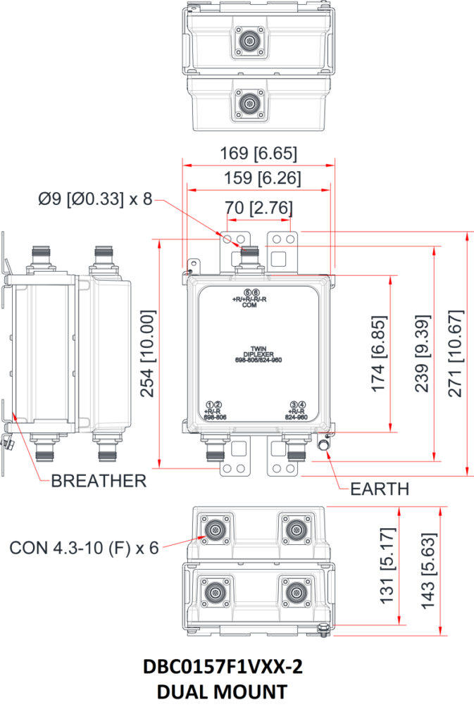
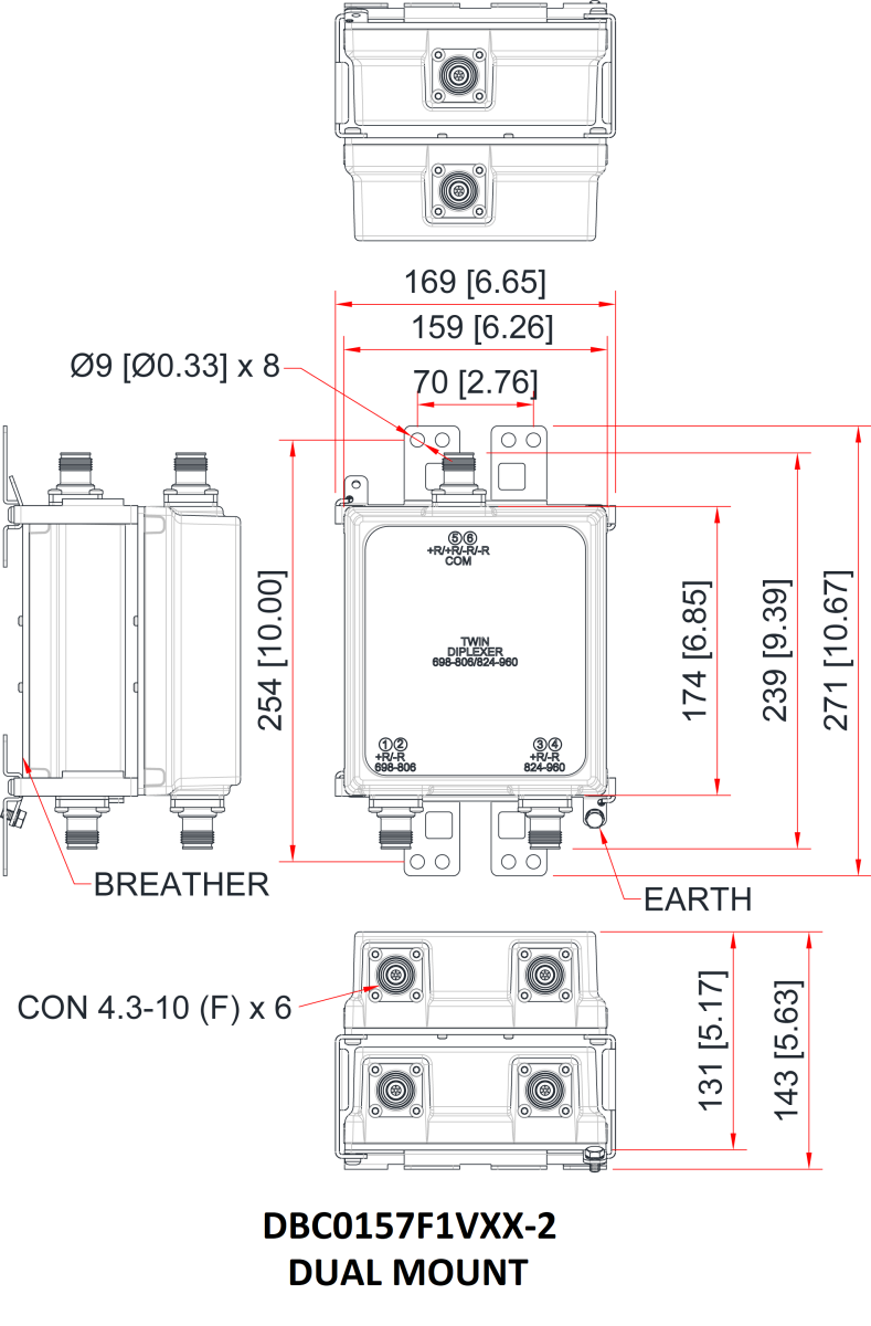
| Dimensions H x D x W (single unit) | 159 x 174 x 62mm | 6.25 x 6.85 x 2.44in | ||||||||||||||
| Dimensions H x D x W (twin unit) | 159 x 174 x 131 mm | 6.25 x 6.85 x 5.15in | ||||||||||||||
| Weight | 2.6kg | 5.73lbs (single unit) 4.3kg / 9.47lbs (twin unit) |
||||||||||||||
| Finish | NCS 1502-R (light grey) | ||||||||||||||
| Connectors | 4.3-10 (F) x 3 long neck (single unit) 4.3-10 (F) x 6 long neck (twin unit) |
||||||||||||||
| Mounting | Pole/wall bracket supplied with two metal clamps for 40-140 mm diameter poles | ||||||||||||||
ORDERING INFORMATION |
|||||||||||||||
| PART NUMBER | CONFIGURATION | OPTIONAL FEATURES | CONNECTORS | DC/AISG CONFIGURATION | |||||||||||
| DBC0157F1V10-1 | 1 in / 2 out | FIXED DC FACTORY CONFIGURABLE |
4.3-10 (F) | NO DC | |||||||||||
| DBC0157F1V10-2 | 2 in / 4 out | FIXED DC FACTORY CONFIGURABLE |
4.3-10 (F) | NO DC | |||||||||||
| DBC0157F1V11-1 | 1 in / 2 out | FIXED DC FACTORY CONFIGURABLE |
4.3-10 (F) | DC ON 850-900 | |||||||||||
| DBC0157F1V11-2 | 2 in / 4 out | FIXED DC FACTORY CONFIGURABLE |
4.3-10 (F) | DC ON 850-900 | |||||||||||
| DBC0157F1V12-1 | 1 in / 2 out | FIXED DC FACTORY CONFIGURABLE |
4.3-10 (F) | DC ON 700 | |||||||||||
| DBC0157F1V12-2 | 2 in / 4 out | FIXED DC FACTORY CONFIGURABLE |
4.3-10 (F) | DC ON 700 | |||||||||||
| DBC0157F1V13-1 | 1 in / 2 out | FIXED DC FACTORY CONFIGURABLE |
4.3-10 (F) | DC TO ALL PATH | |||||||||||
| DBC0157F1V13-2 | 2 in / 4 out | FIXED DC FACTORY CONFIGURABLE |
4.3-10 (F) | DC TO ALL PATH | |||||||||||
| Note: DC autosense versions available, contact Kaelus for information | |||||||||||||||
ELECTRICAL BLOCK DIAGRAM |
|||||||||||||||
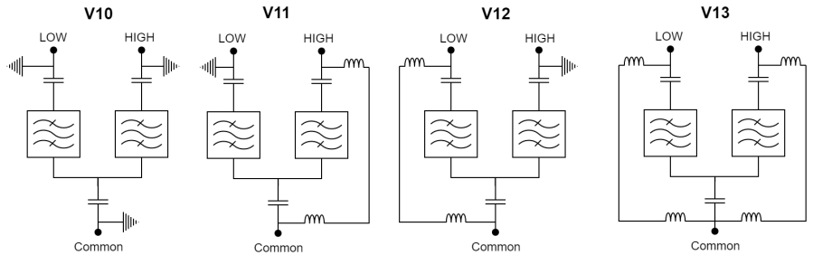
| DBC0157F1VXX-Z where XX denotes the DC path variant Z denotes the mounting : “-1” = single mount and “-2” = dual mount LOW port is 700 band HIGH port is 850-900 band |
MECHANICAL BLOCK DIAGRAM |