BANDPASS FILTER, GSMR900
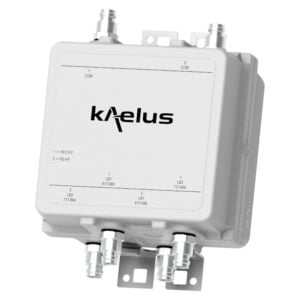
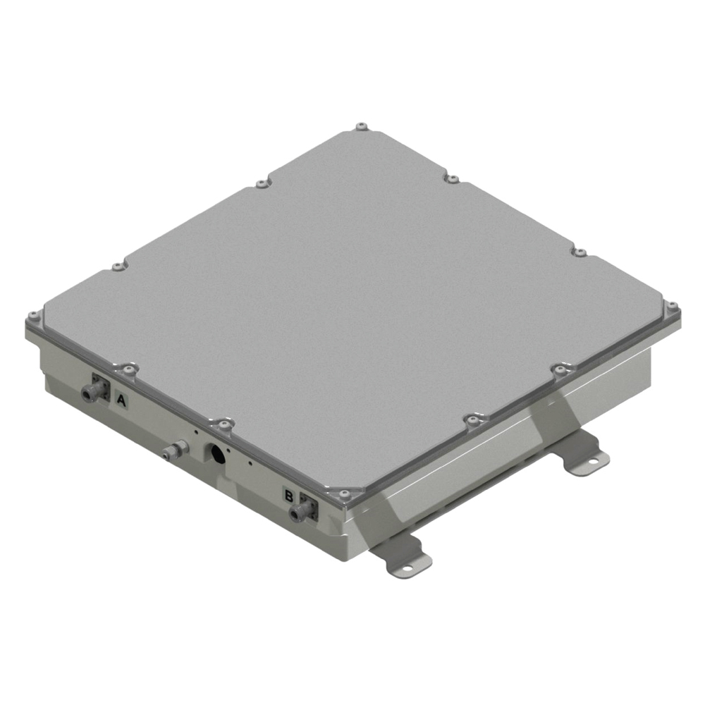
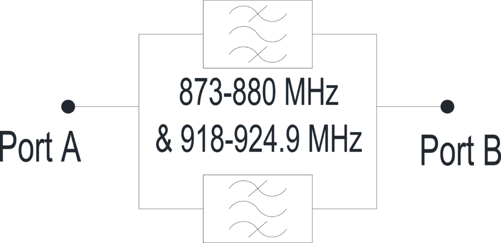
This GSM-R filter is a two port unit with the ability to simultaneously pass both uplink and downlink GSM-R signals.
FEATURES
- Designed for GSM-R cab radio use
- Suitable for indoor applications
- Narrow guard band to EGSM downlink signals
TECHNICAL SPECIFICATIONS |
|||||||||||||||
| BAND NAME | DOWNLINK (BTS TX) | UPLINK (BTS RX) | |||||||||||||
| RF PERFORMANCE | |||||||||||||||
| Passband | 918 – 924.9MHz | 873 – 880MHz | |||||||||||||
| Bandwidth | 6.9MHz | 7MHz | |||||||||||||
| Insertion loss | 918-924.8MHz- 2.0dB maximum / 1.0dB typical at mid-band 924.9MHz- 3.0dB maximum |
2.0dB max at band edge, 1.0dB typ midband | |||||||||||||
| Return loss | 15dB minimum | 15dB minimum | |||||||||||||
| Maximum input power | 20W maximum (average) / 200W (PEP) | NA | |||||||||||||
| REJECTION CHARACTERISTIC | |||||||||||||||
| 925.4MHz | 15dB minimum | ||||||||||||||
| 926 – 960MHz | 30dB minimum | ||||||||||||||
| ELECTRICAL | |||||||||||||||
| Impedance | 50ohms | ||||||||||||||
| Intermodulation products | <-150dBc with 2 x 37dBm carriers, reflected mode, in RX band | ||||||||||||||
| ENVIRONMENTAL | |||||||||||||||
| For further details of environmental compliance, please contact Kaelus. | |||||||||||||||
| Temperature range | -25ºC to +70ºC | -13°F to +158°F, EN 50155, EN 60068 | ||||||||||||||
| Ingress protection | IP54 | ||||||||||||||
| Altitude | 1,000m | 3,300ft max, EN 50125.1 | ||||||||||||||
| Compliance | EN 50155, EN 61373 Shock and Vibration EN 50155 4.1.4 Relative Humidity EN 50121-3-2 EMC Rolling Stock EN 45545 Fire Protection on Railway Vehicles ETSI 300-019-2-1 Storage and Transport Environmental RoHS |
||||||||||||||
| MECHANICAL | |||||||||||||||
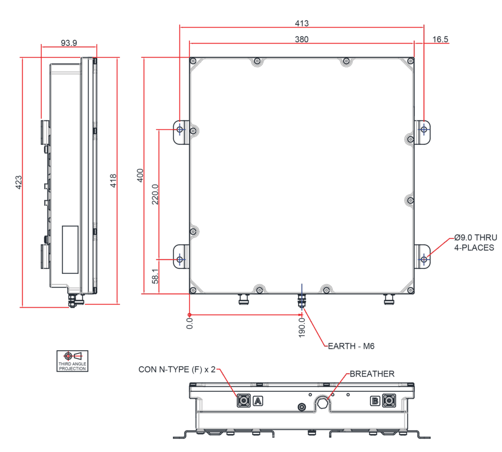
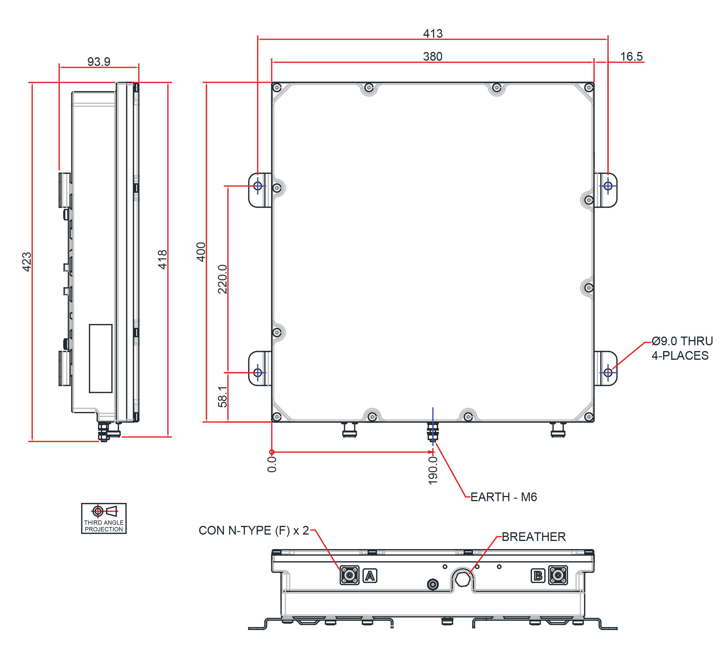
| Dimensions H x D x W | 400 x 380 x 78mm | 15.75 x 14.96 x 3.07in (excluding brackets) | ||||||||||||||
| Weight | 17.0kg | 37.48lbs | ||||||||||||||
| Finish | Powder coated, light grey (RAL7035) | ||||||||||||||
| Connectors | N type (F) X 2 | ||||||||||||||
| Mounting | Customer specific | ||||||||||||||
ORDERING INFORMATION |
|||||||||||||||
| PART NUMBER | DESCRIPTION | ||||||||||||||
| DDF9006F1V1-1 | Dual Duplexed Filter, GSM900 | ||||||||||||||
| DCI9001F1V1-1 | DC Injector | ||||||||||||||
| SWT9003F1V1-1 | Switch assembly for DDF9006F1V1-1 | ||||||||||||||
| GSR0003F1V1-1 | System including DDF9006F1V1-1 and SWT9003F1V1-1 | ||||||||||||||
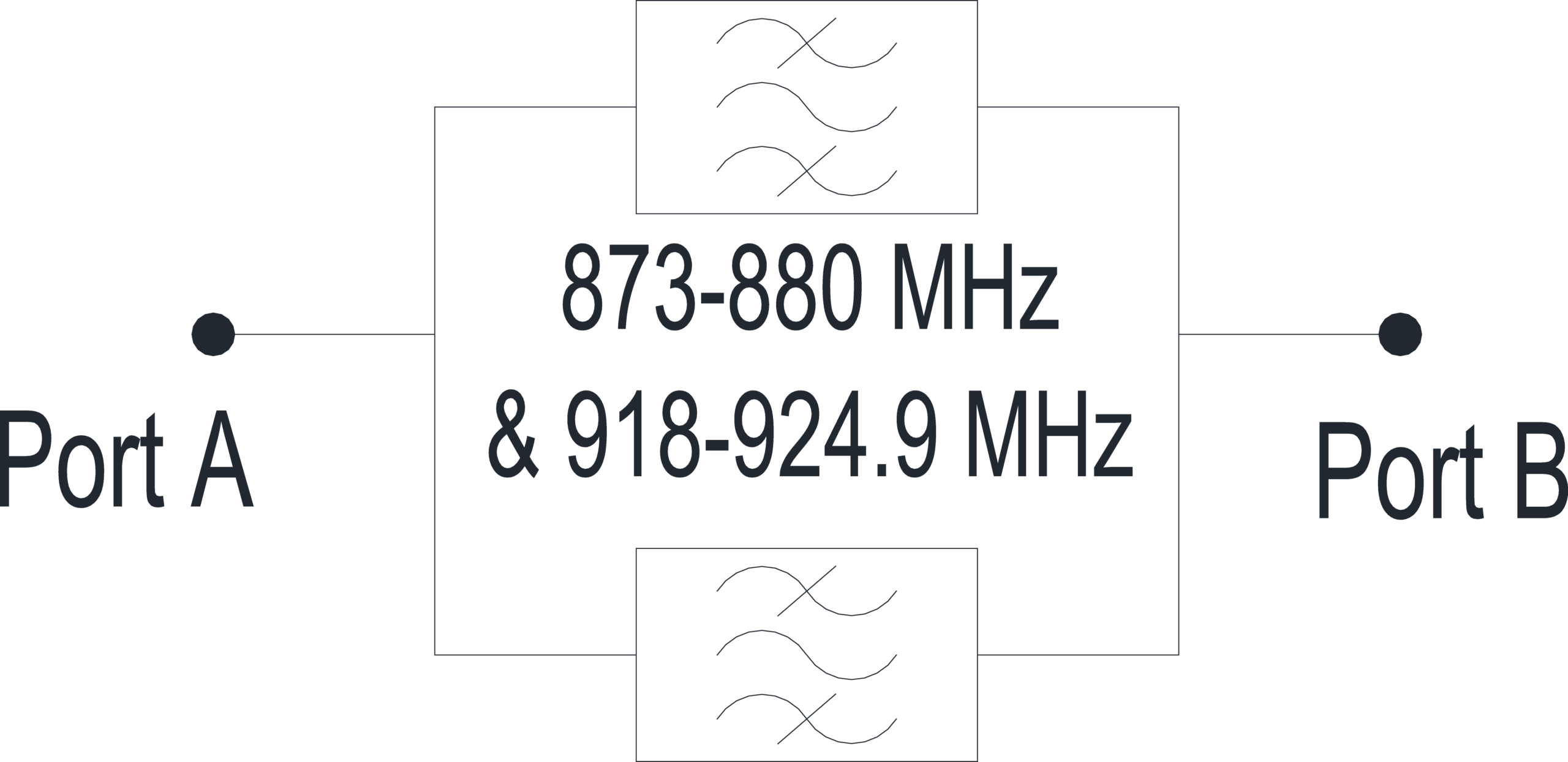
ELECTRICAL BLOCK DIAGRAM |
MECHANICAL BLOCK DIAGRAM |