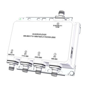
TRIPLEXER 800-900/1800/2100
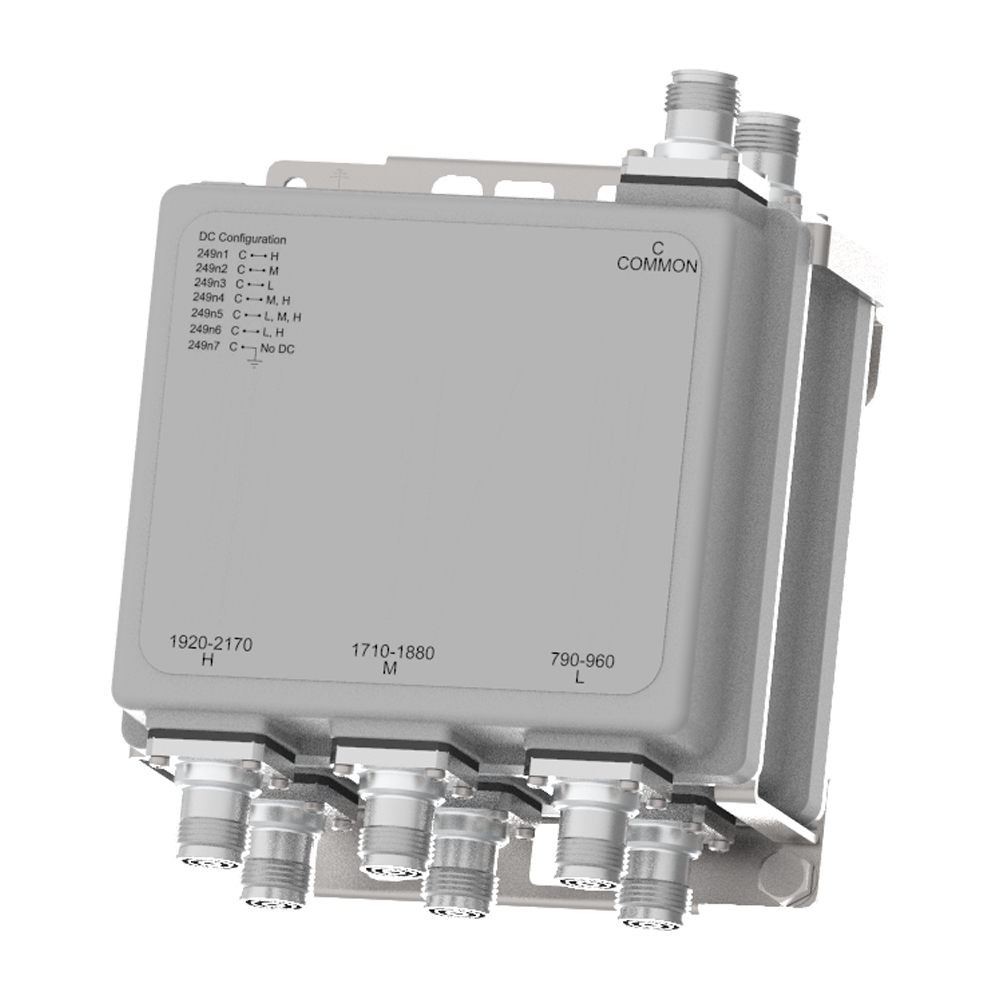
The Kaelus MI-249 is a bi-directional triplexer, designed to combine or split 700-900/1800/2100 MHz. The MI-249 provides low insertion loss and high return loss with excellent passive inter-modulation performance in an extremely small and lightweight IP67 capable package
FEATURES
- Enables antenna & coax sharing for 800-900/1800/2100 MHz bands systems.
- Compact & lightweight – perfect for Small Cell applications
- Low insertion loss & high return loss
- High passive IM performance
- Single and dual models available
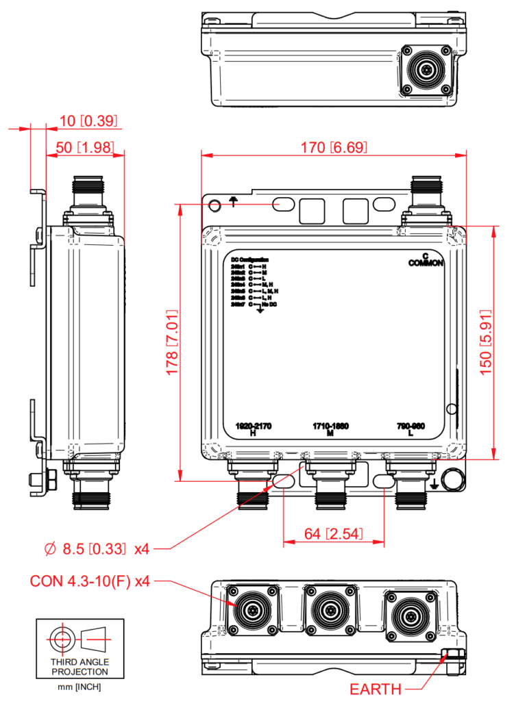
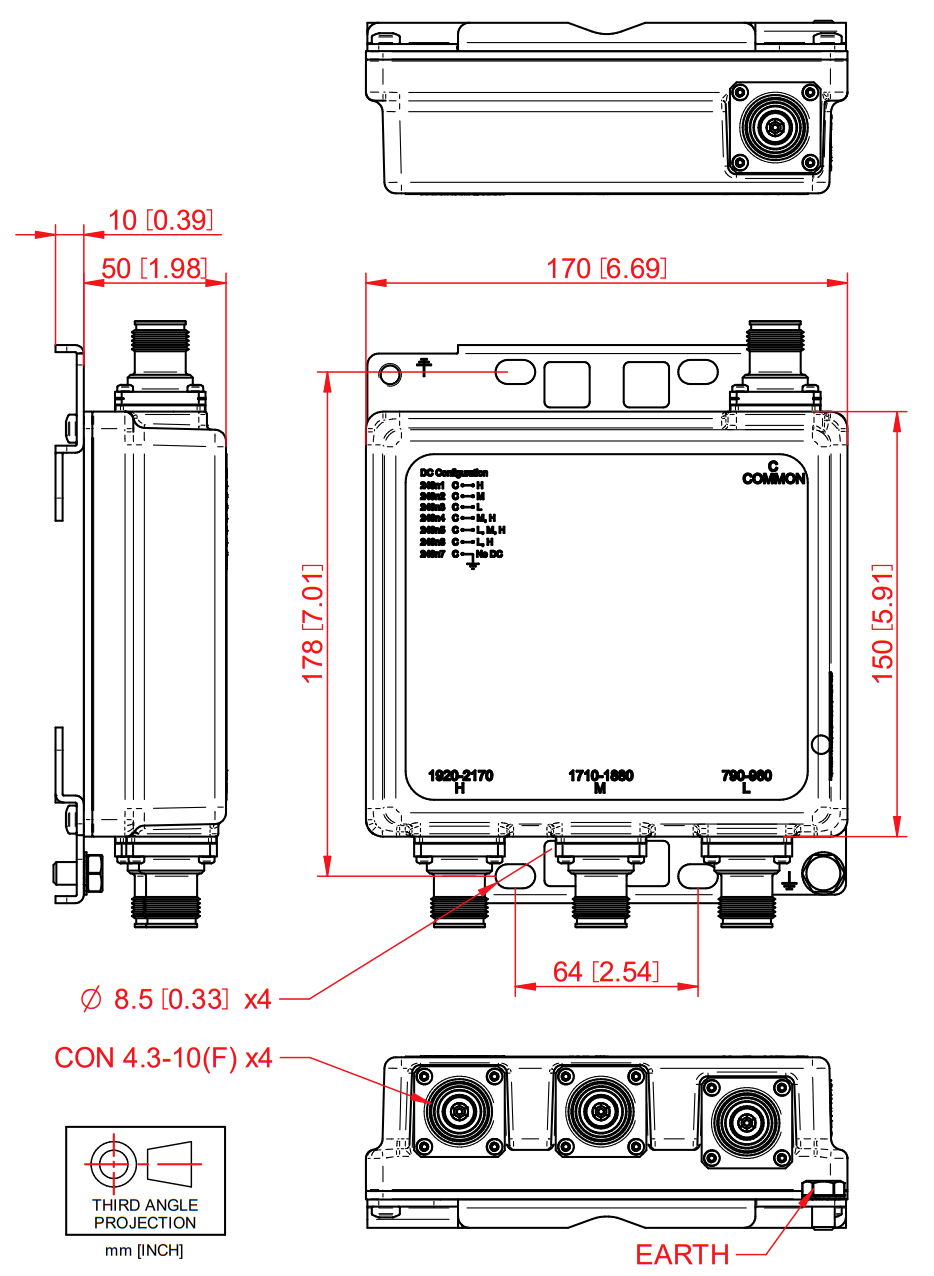
- 7/16 (F) or 4.3-10 (F) connectors
- Hard Wired and DC Autosense versions available
- Provisions for wall or mast mounting
| BAND NAME |
800-900 |
1800 |
2100 |
| Passband |
790 – 960 MHz |
1710 – 1880 MHz |
1920 – 2170 MHz |
| Insertion loss |
0.1 dB typical, 0.2 dB maximum |
0.2 dB typical, 0.4 dB maximum |
0.2 dB typical, 0.5 dB maximum |
| Return loss |
> 18 dB maximum |
> 18 dB maximum |
> 18 dB maximum |
| Maximum input power |
250W |
| Intermodulation products |
-160 dBc at 2 x 43dBm TX Carrier |
| Rejection |
50 dB minimum in 1710 – 1880 MHz and 1920 – 2170 MHz |
50 dB minimum in 790 – 960 MHz and 1920 – 2170 MHz |
50 dB minimum in 790 – 1880 MHz |
|
| Insertion loss |
1 dB max |
| Return loss |
12 dB min |
| Input voltage range |
8 – 30 V DC max 0.3 W |
| DC current rating |
3 A continuous, Drop max 2.4 V |
| Compliance |
3GPP TS 37.461 |
| Temperature range |
-40 ºC to +65 ºC | -40 ºF to +149 ºF |
| Ingress protection |
IP67 |
| Lightning protection |
5 kA maximum (8/20 us) |
| MTBF |
> 1,000,000 Hours |
| Compliance |
ETSI EN 300 019-1-4 class 4.1E, RoHS |
| Feature |
Single Mount |
Dual Mount |
| Dimensions H x D x W |
170 x 150 x 50 mm I 6.69 x 5.91 x 1.97 in |
170 x 150 x 109 mm I 6.69 x 5.91 x 4.29 in |
| Volume |
1.3 l |
2.8 l |
| Weight |
3 kg I 6.61 lb |
5.5 kg I 12.13 lb |
| Finish |
Painted, NCS 1502-R ( Light Grey ) |
| Mounting |
Hose clamps or wall mount ( Supporter pole Diameter: 40 – 140 mm ) |
| Feature |
Single Mount With Auto-sense |
Dual Mount With Auto-sense |
| Dimensions H x D x W |
170 x 150 x 62 mm I 6.69 x 5.91 x 1.97 in |
| Volume |
1.6 l |
| Weight |
3,2 kg I 6.61 lb |
| Finish |
Painted, NCS 1502-R ( Light Grey ) |
| Mounting |
Hose clamps or wall mount ( Supporter pole Diameter: 40 – 140 mm ) |
| PART NUMBER |
CONFIGURATION |
OPTIONAL FEATURES |
CONNECTORS |
DC/AISG CONFIGURATION |
| MI-2490n |
Single Mount |
BASE MODEL |
7/16 (F) |
Refer to DC /AISG table |
| MI-2491n |
Dual Mount |
BASE MODEL |
7/16 (F) |
Refer to DC /AISG table |
| MI-2493n |
Single Mount |
BASE MODEL |
4.3-10 (F) |
Refer to DC /AISG table |
| MI-2494n |
Dual Mount |
BASE MODEL |
4.3-10 (F) |
Refer to DC /AISG table |
| MI-249nA |
Auto-sense |
| MI-249n1 |
DC TO 2100 |
| MI-249n2 |
DC TO 1800 |
| MI-249n3 |
DC TO 800 – 900 |
| MI-249n4 |
DC To 1800 and 2100 |
| MI-249n5 |
DC TO ALL |
| MI-249n6 |
DC TO 800 – 900 and 2100 |
| MI-249n7 |
DC Block |
| MI-249nA.1 |
FPO 800 – 900, 1800 and 2100 |
| MI-249nA.2 |
XOR to 800 – 900, 1800 and 2100 |
| MI-249nA.3 |
800 – 900 Priority 1, 1800 Priority 2 and 2100 Priority 3 |
| MI-249nA.4 |
2100 Priority 1, 1800 Priority 2 and 800 – 900 Priority 3 |
| MI-249nA.5 |
1800 Priority 1, 2100 Priority 2 and 800 – 900 Priority 3 |
| MI-249nA.6 |
1800 Priority 1, 800 – 900 Priority 2 and 2100 Priosrity 3 |
| MI-249nA.7 |
800 – 900 Priority 1, 2100 Priority 2 and 1800 Priority 3 |
| MI-249nA.8 |
2100 Priority 1, 800 – 900 Priority 2 and 1800 Priority 3 |