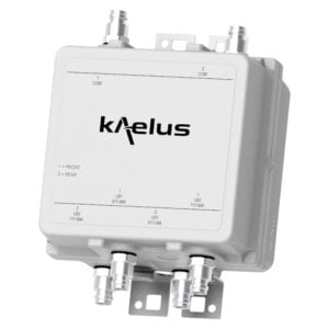
SMART BIAS TEE – ANT SIDE/TOP OF THE TOWER
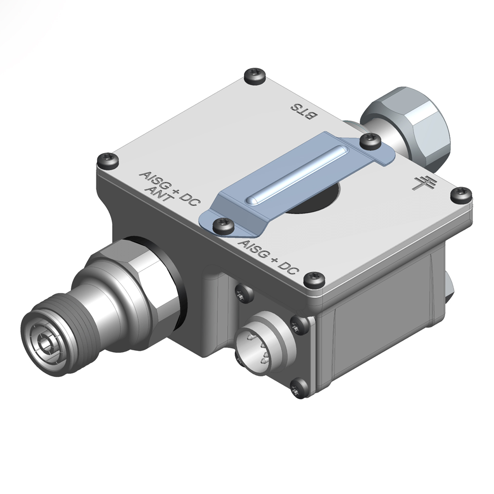
The Kaelus SBT0003 provides a flexible Smart Bias Tee solution allowing for AISG and DC to be placed onto a feeder at the bottom of the tower or extracted from the feeder at the top. Operating across all the cellular frequency bands, the SBT0003 provides the following additional benefits.
FEATURES
- 555-3800MHz operation provides coverage in 600MHz through 3.5GHz frequency bands
- Available in top of the tower or bottom of the tower applications
- Primary surge protection limits the voltage let-through from the feeder to the DC port
- Multiple connector configurations to allow for different installation scenarios
- IP67 for continuous outdoor operation
TECHNICAL SPECIFICATIONS |
| RF TO RF+AISG | |||||||||||||||
| Passband | 555 – 3800MHz | ||||||||||||||
| Insertion loss | 0.1dB maximum | ||||||||||||||
| Return loss | 20dB minimum | ||||||||||||||
| Maximum input power | 750W CW/5kW PEP | ||||||||||||||
| Intermodulation products | -160dBc (IM3) maximum @ 2 x 20W CW carriers | ||||||||||||||
| RF impedance | 50Ohms | ||||||||||||||
| AISG TO RF+ AISG | |||||||||||||||
| AISG version | 2.0 compliant | ||||||||||||||
| DC voltage rating | +10 to +30V | ||||||||||||||
| DC current rating | 2.7A continuous, 4A (10 sec at startup) peak | ||||||||||||||
| DC resistance, AISG port to RF + AISG | 0.5Ohm typical | ||||||||||||||
| Isolation, 555 – 3800MHz | 65dB minimum | ||||||||||||||
| Return loss 2.076 – 2.276MHz | 10dB minimum | ||||||||||||||
| ENVIRONMENTAL | |||||||||||||||
| For further details of environmental compliance, please contact Kaelus. | |||||||||||||||
| Temperature range | -40ºC to +65ºC | -40°F to +149°F, indoor | ||||||||||||||
| Ingress protection | IP67 / outdoor | ||||||||||||||
| Altitude | 3km /10k ft maximum | ||||||||||||||
| Lightning protection | RF: ±5kA (8/20µs), AISG: 2kA (8/20µs) | ||||||||||||||
| MTBF | >1,000,000 hours | ||||||||||||||
| Compliance | 3GPP, TS25.461, RoHS compliant | ||||||||||||||
| Surge protection | Multi-stage network | ||||||||||||||
| MECHANICAL | |||||||||||||||
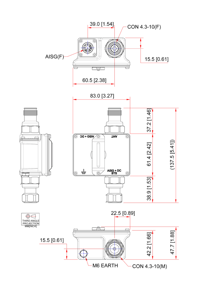
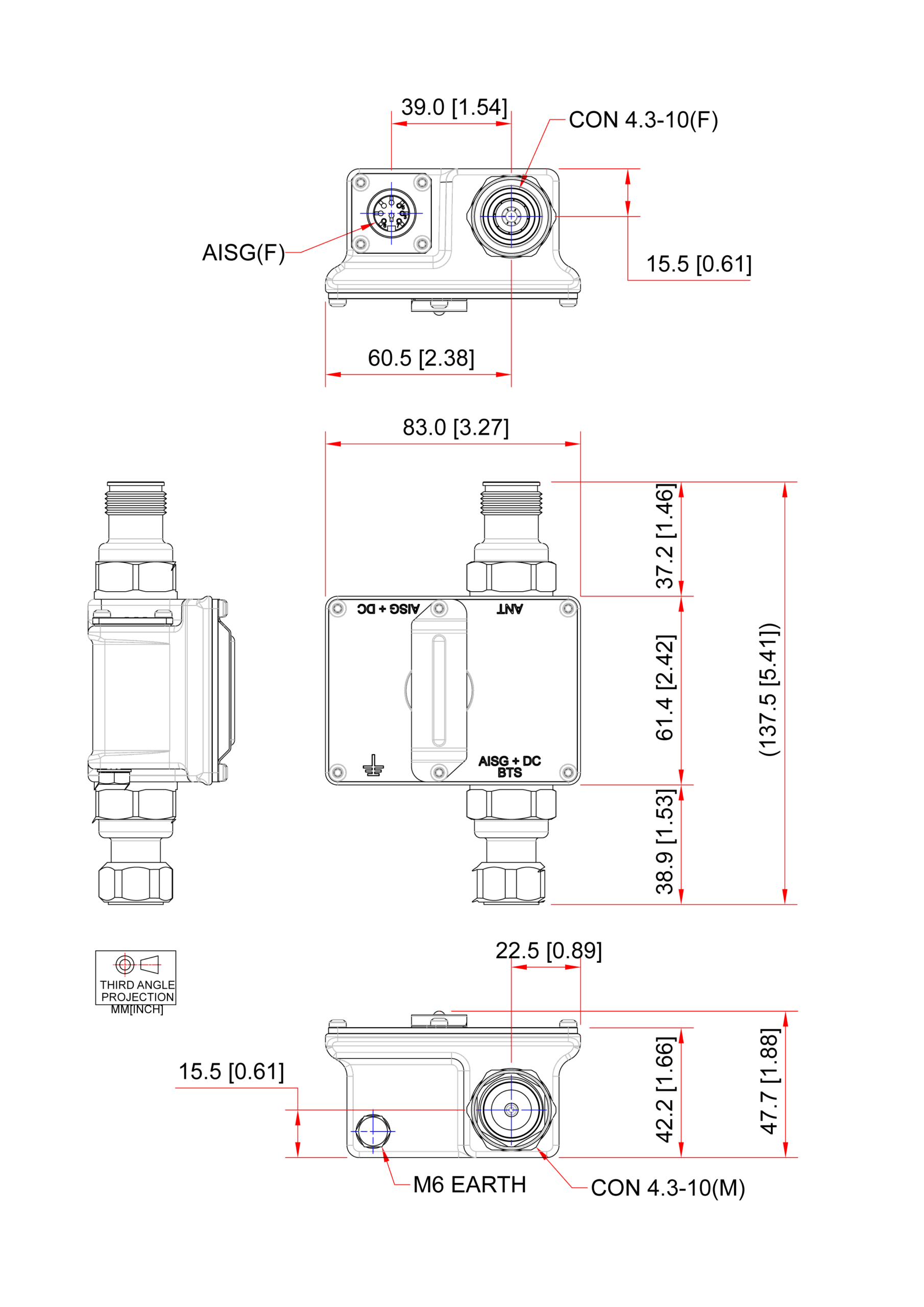
| Dimensions H x D x W | 61x83x48mm | 2.40×3.27×1.89in | ||||||||||||||
| Weight | 0.4kg | 0.88lbs | ||||||||||||||
| Finish | Aluminium | ||||||||||||||
| Connector 1 | RF: 2 x 4.3/10, gender varies see ordering information for details | ||||||||||||||
| Connector 2 | AISG/DC: V1 and V3: AISG male (bottom of feeder) connect to controller V2 and V4: AISG female (end of feeder) connect to RETs |
||||||||||||||
| Protective earth | M6 stud | ||||||||||||||
ORDERING INFORMATION |
|||||||||||||||
| PART NUMBER | DESCRIPTION | ||||||||||||||
| SBT0003F1V1 | SMART BIAS T, 4.3-10M BTS 4.3-10F ANT AISGM STD bottom of the tower | ||||||||||||||
| SBT0003F1V2 | SMART BIAS T, 4.3-10F BTS 4.3-10M ANT AISGF STD top of the tower | ||||||||||||||
| SBT0003F1V3 | SMART BIAS T, 4.3-10F BTS 4.3-10M ANT AISGM STD bottom of the tower | ||||||||||||||
| SBT0003F1V4 | SMART BIAS T, 4.3-10M BTS 4.3-10F ANT AISGF STD top of the tower | ||||||||||||||
OPTIONAL ACCESSORIES |
|||||||||||||||
| PART NUMBER | DESCRIPTION | ||||||||||||||
| ACU0001F1V1 | AISG controller-3 way-rack mounted | ||||||||||||||
| R18-0749-1 | Cable assembly – AISG outdoor cable-male to female – 1m | ||||||||||||||
| R18-0749-3 | Cable assembly – AISG outdoor cable-male to female – 3m | ||||||||||||||
| R18-0749-5 | Cable assembly – AISG outdoor cable-male to female – 5m | ||||||||||||||
| R18-0749-10 | Cable assembly – AISG outdoor cable-male to female – 10m | ||||||||||||||
| R18-0749-15 | Cable assembly – AISG outdoor cable-male to female – 15m | ||||||||||||||
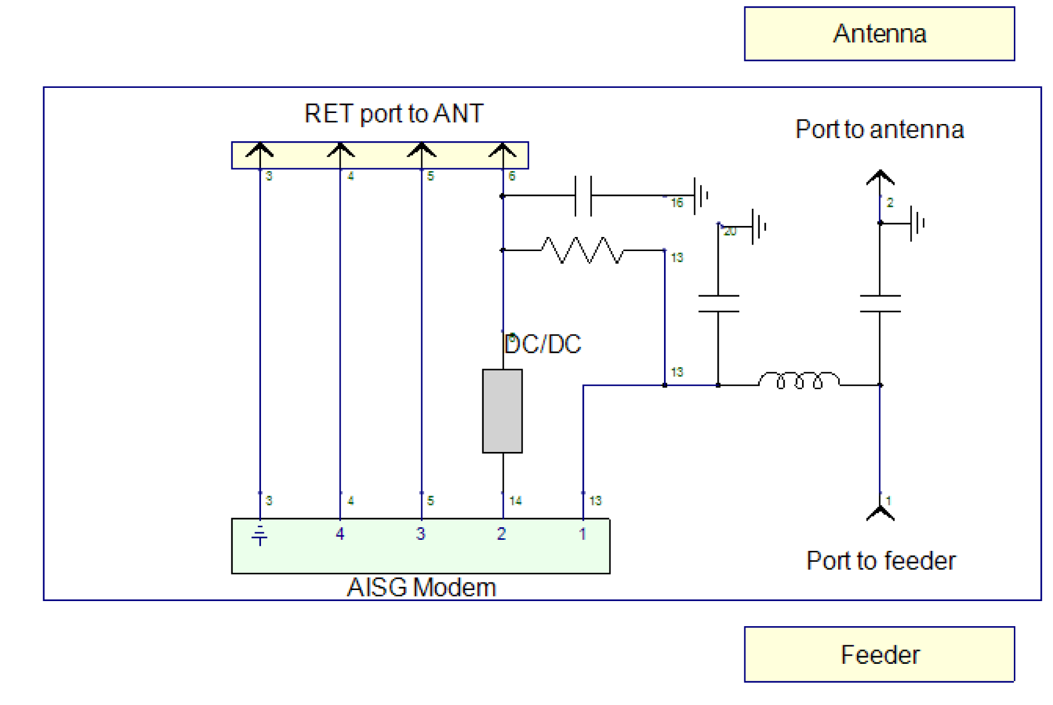
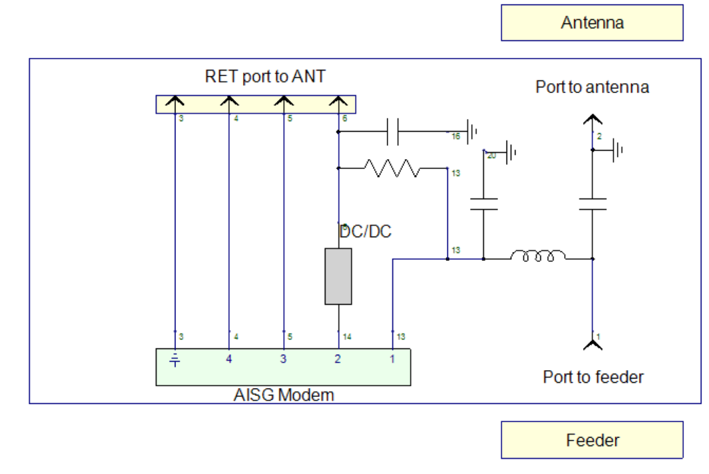
ELECTRICAL BLOCK DIAGRAM |
MECHANICAL BLOCK DIAGRAM |