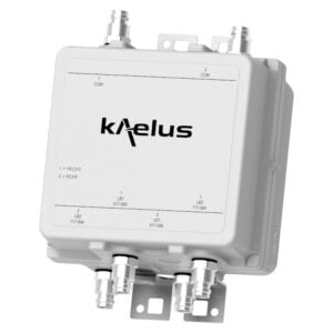
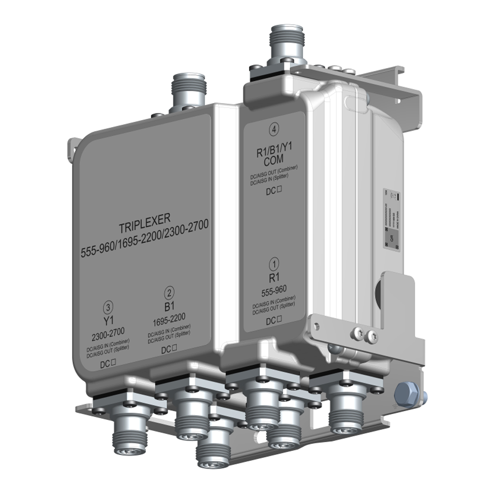
TWIN TRIPLEXER 555-960/1695-2200/2300-2700
Kaelus world-proven outdoor solutions provide strong RF performance coupled with rugged operation. The TBCT038 provides the following features:
FEATURES
- Enables feeder sharing of various technologies including but not limited to LTE700, LTE800, EGSM900, PCS, WCS, 1800, 2300TDD, 2100, 2600
- Low insertion loss and high isolation
- Multiple DC/AISG bypass configurations available with built-in lightning protection
- Low passive IM performance
TECHNICAL SPECIFICATIONS |
|||||||||||||||
| BAND NAME | 555 – 960 | 1695 -2200 | 2300 – 2700 | ||||||||||||
| Passband | 555 – 960MHz | 1695 – 2200MHz | 2300 – 2700MHz | ||||||||||||
| Insertion loss | <0.2dB typical | <0.2dB typical | <0.2dB typical | ||||||||||||
| Return loss | >20dB | >20dB | >20dB | ||||||||||||
| Maximum input power | 250W (average) / 2kW (PEP) | 250W (average) / 2kW (PEP) | 250W (average) / 2kW (PEP) | ||||||||||||
| Intermodulation products | <-165 dBc typ at 2 x +43dBm TX Carrier | ||||||||||||||
| Attenuation in 555 – 960MHz | N/A | > 50dB | > 50dB | ||||||||||||
| Attenuation in 1695 – 2200MHz | > 50dB | N/A | > 50dB | ||||||||||||
| Attenuation in 2300 – 2700MHz | > 50dB | > 50dB | N/A | ||||||||||||
| ELECTRICAL | |||||||||||||||
| Impedance | 50Ohms | ||||||||||||||
| ENVIRONMENTAL | |||||||||||||||
| For further details of environmental compliance, please contact Kaelus. | |||||||||||||||
| Temperature range | -40ºC to +65ºC | -40°F to 149°F | ||||||||||||||
| Ingress protection | IP67 | ||||||||||||||
| Lightning protection | 5kA 8/20 µs | ||||||||||||||
| MTBF | > 1,000,000 Hours | ||||||||||||||
| Compliance | ETS 300 019 1-4 (OPERATIONAL) ETS 300 019 1-1 (STORAGE) |
||||||||||||||
| DC / AISG | |||||||||||||||
| DC/AISG path is factory configurable, see ordering information | |||||||||||||||
| Passband | 0 – 3MHz | ||||||||||||||
| Insertion loss | 1dB maximun | ||||||||||||||
| Return loss | 12dB minimun | ||||||||||||||
| Input voltage range | ± 30V | ||||||||||||||
| DC current rating | 3A continuous | ||||||||||||||
| Compliance | 3GPP TS 25.461 | ||||||||||||||
| MECHANICAL | |||||||||||||||
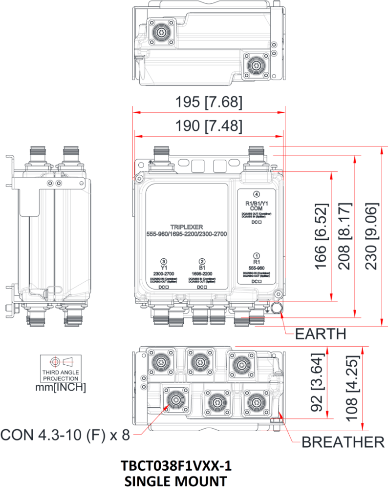
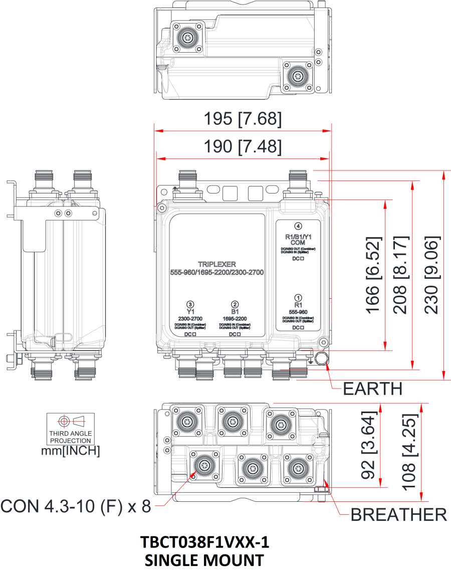
| Dimensions H x D x W | 166 x 92 x 190mm | 6.5 x 3.6 x 7.5in | ||||||||||||||
| Weight | 4.7kg | 10.31lbs max | ||||||||||||||
| Finish | Painted, NCS 1502-R | ||||||||||||||
| Connectors | 4.3-10 (F) x 8 long neck | ||||||||||||||
| Wind Load | Front 207N, Side 37N (Single) Front 231N, Side 97N (Twin) At 74m/s (AS/NZS 1170-2-2011 Structural design – Wind actions – Cyclone areas) |
||||||||||||||
| Mounting | Pole/wall bracket supplied with two metal clamps for 45-178 mm diameter poles | ||||||||||||||
ORDERING INFORMATION |
|||||||||||||||
| PART NUMBER | CONFIGURATION | OPTIONAL FEATURES | CONNECTORS | DC/AISG CONFIGURATION | |||||||||||
| TBCT038F1V10-1 | 2 in / 6 out | FIXED DC FACTORY CONFIGURABLE |
4.3-10 (F) | NO DC | |||||||||||
| TBCT038F1V11-1 | 2 in / 6 out | FIXED DC FACTORY CONFIGURABLE |
4.3-10 (F) | DC TO 2300-2700MHz | |||||||||||
| TBCT038F1V12-1 | 2 in / 6 out | FIXED DC FACTORY CONFIGURABLE |
4.3-10 (F) | DC TO 1695-2200MHz | |||||||||||
| TBCT038F1V13-1 | 2 in / 6 out | FIXED DC FACTORY CONFIGURABLE |
4.3-10 (F) | DC TO 555-960MHz | |||||||||||
| TBCT038F1V14-1 | 2 in / 6 out | FIXED DC FACTORY CONFIGURABLE |
4.3-10 (F) | DC TO ALL PATH | |||||||||||
| Note: DC autosense versions available, contact Kaelus for information | |||||||||||||||
ELECTRICAL BLOCK DIAGRAM |
|||||||||||||||
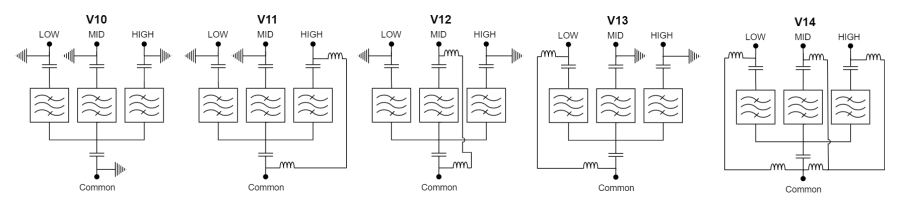
| TBCT038F1VXX-Z where XX denotes the DC path variant Z denotes the mounting : “-1” = single mount and “-2” = dual mount LOW port is 555-960MHz band MID port is 1695-2200MHz band HIGH port is 2300-2700MHz band |
MECHANICAL BLOCK DIAGRAM |