TWIN TMA 700, LOWPASS
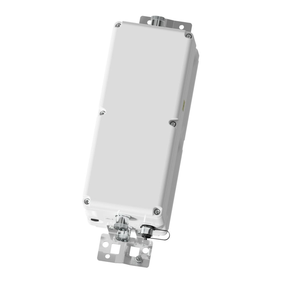
Designed to be deployed in 700, 850/900MHz shared antenna systems, the Kaelus TMA2094 provides gain at the 700MHz uplink band while allowing 850/900 services to pass through to the antenna thereby saving OPEX and CAPEX.
FEATURES
- Improved base station sensitivity through gain in 700Mhz band
- Bypass for 850/900 bands with internal diplexing of the 807-960 and 700MHz bands
- Rejection of digital TV broadcast channels
- Hardware and software configuration using AISG “Personality” upload
- Fail safe bypass mode with lightning protection
- High linearity and low noise performance
| Passband |
768 – 803MHz |
| Bandwidth |
35MHz |
| Return loss |
18dB minimum |
| Insertion loss |
0.2dB typical, 0.4dB maximum |
| Group delay variation |
70ns maximum |
| Absolute group delay |
80ns maximum |
| Maximum input power with no damage |
150W (average) / 1.5kW (PEP) |
| Intermodulation @ antenna ports |
-150dBc maximum in RX band with 2 x 20W carriers |
| Passband |
713 – 748MHz |
| Bandwidth |
35MHz |
| Nominal gain |
16dB minimum |
| Gain variation over frequency, temperature |
± 1dB maximum |
| Noise figure |
1.2dB typical, 1.6dB maximum |
| Return loss |
18dB minimum operating, 12dB minimum in bypass mode |
| Bypass loss |
2.5dB typical, 3.2dB maximum |
| Group delay variation |
150ns maximum |
| Absolute group delay |
250ns maximum |
| Output IP3 |
+30dBm typical |
| Maximum input power with no damage |
12dBm maximum |
| RX in filter rejection |
50dB @ 50 – 694MHz |
| Passband |
807 – 960MHz |
| Return loss |
18dB minimum |
| Insertion loss |
0.2dB typical, 0.4dB maximum |
| Group delay variation |
30ns maximum |
| Absolute group delay |
40ns maximum |
| Maximum input power with no damage |
160W (average) / 1.5kW (PEP) |
| Intermodulation @ antenna ports |
-150dBc maximum in RX band with 2 x 20W carriers |
| DC supply voltage |
8.5V to 30V DC, case is DC ground |
| DC supply voltage via BTS-RF cable |
Through BTS connectors |
| DC supply current, normal mode |
150 ± 20mA per port, 1.3W @ 8.5V, 4.5W @ 30V typical |
| DC supply current, alarm mode programmable range |
220 ± 20mA per port, 3.3W @ 15V per port typical |
| DC supply voltage |
+8V to +30V DC |
| AISG version |
2.0 (1.1 optional) |
| Supply current, AISG mode |
220mA @ 8.5V, 70mA @ 30V typical |
| Voltage drop, BTS to AISG port |
1.5V maximum at 2A |
| Power consumption, AISG mode |
1.9W @ 8.5V, 2.1W @ 30V typical |
| AISG connector, current rating |
IEC60130-9, 8-pin female, < 4A peak, 2A continuous, pin 6 |
| Field firmware upgradable |
Yes |
| Mode of operation |
Current draw on ANT1 port |
Assumption |
“Autosense + Protection” switch status |
Comment |
| CWA mode |
Any |
Unit in CWA mode |
Open |
No DC will be passed on to ANT1 |
| AISG mode |
Current<4A |
Device present or open circuit on ANT1, Unit in AISG Mode |
Close |
AISG signal (sub-carrier) will be supplied thru to ANT1 |
| AISG mode |
Current >4A |
DC short circuit or low DC resistance present on ANT1 port |
Open |
Attempts are made periodically to re-connect. TMA2094FxxVx-1 will operate in AISG mode. |
| Temperature range |
-10º to +55ºC | -5º to +131ºF |
| Ingress protection |
IP67 |
| Altitude |
2,600m | 8,530ft maximum |
| Lightning protection |
IEC61312-1, RF: ±5kA maximum (8/20us), AISG: ±2kA maximum (8/20us) |
| MTBF |
>1,000,000 (hours) |
| Compliance |
EMC:EN301 489, ETSI EN 300 019 class 4.1, RoHS |
| Dimensions H x D x W |
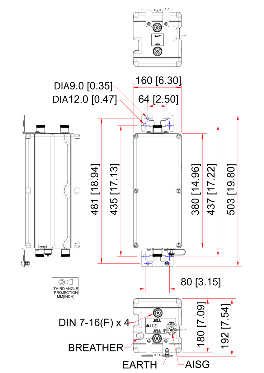
380 x 160 x 180mm | 14.96 x 6.3 x 7.1in (excluding brackets and connectors) |
| Weight |
16kg | 35.27lbs |
| Finish |
Painted, light grey (RAL7035) |
| Connectors |
DIN 7-16 (F) x 4 long neck, AISG (F) x 1 |
| Mounting |
Pole/wall bracket supplied with two metal clamps 45-178mm diameter poles |
| PART NUMBER |
CONFIGURATION |
OPTIONAL FEATURES |
CONNECTORS |
| TMA2094F01V2-1 |
TWIN 2 in / 2 out |
STANDARD |
DIN 7-16 (F) |