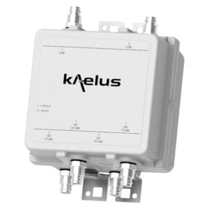
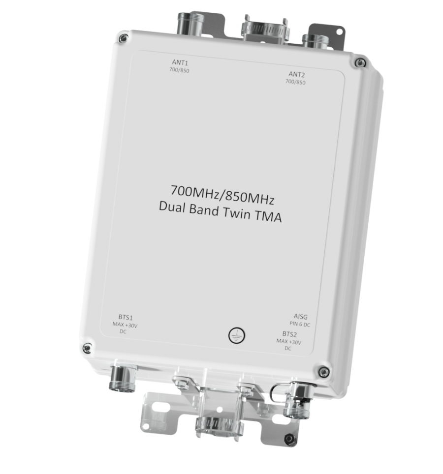
TWIN TMA 700/850
Designed to be deployed in 700, 850MHz shared antenna systems, the Kaelus TMA2105 provides gain at both the 700MHz and 850MHz uplink bands
FEATURES
- Improved base station sensitivity
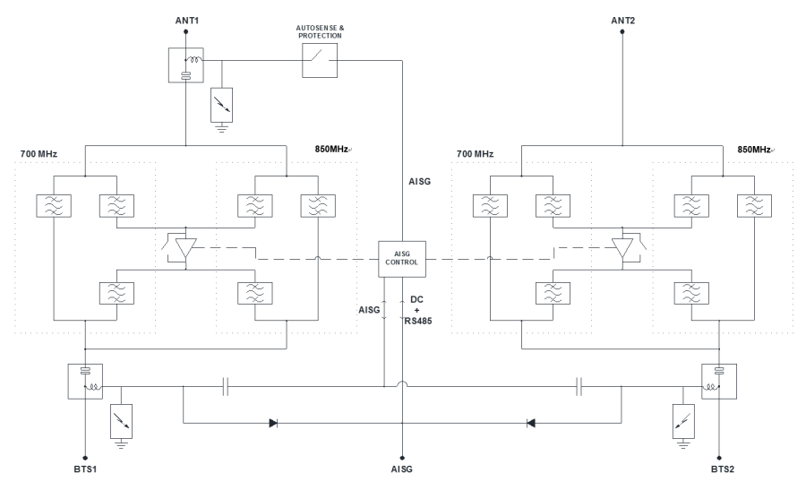
- Internal diplexing of the 700MHz and 850MHz bands allows for single ANT and BTS ports
- Fail safe bypass mode with lightning protection
- Rejection of digital TV broadcast channels
- High linearity and low noise performance
Electrical block diagram
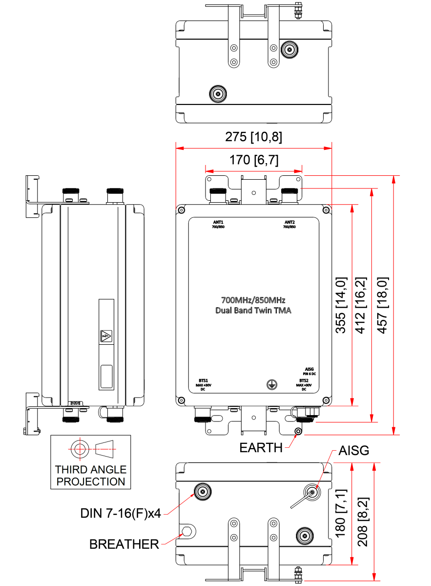
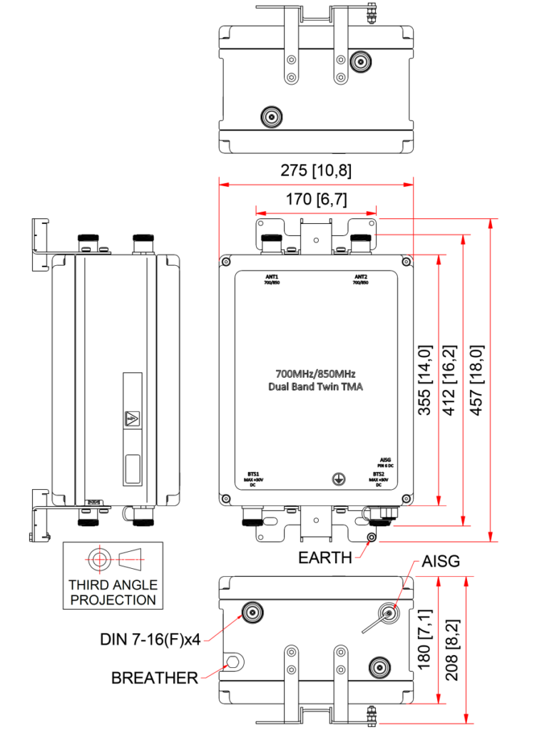
Mechanical block diagram
Technical specifications |
|||||||||||||||
| Band Name | 700 | 850 | |||||||||||||
Downlink |
|||||||||||||||
| Passband | 768 – 803MHz | 875 – 890MHz | |||||||||||||
| Bandwidth | 35MHz | 15MHz | |||||||||||||
| Insertion loss | 0.4dB typical | 0.45dB typical | |||||||||||||
| Return loss | 18dBminimum | ||||||||||||||
| Group delay variation | 40ns maximum across band | 30ns maximum across band | |||||||||||||
| Absolute group delay | 80ns maximum | ||||||||||||||
| Maximum input power | 120W (average) / 1.5kW (PEP) | 160W (average) / 3.2kW (PEP) | |||||||||||||
| Intermodulation products | -150dBc maximum with 2 x 20W carriers (in RX band) | -150dBc maximum with 2 x 20W carriers (in RX band) | |||||||||||||
| Nominal propagation delay | 52ns | 50ns | |||||||||||||
Uplink |
|||||||||||||||
| Passband | 713 – 748MHz | 830 – 845MHz | |||||||||||||
| Bandwidth | 35MHz | 15MHz | |||||||||||||
| Gain | 17dB | 15.5dB minimum | |||||||||||||
| Gain maximum | 18dB | 16.5dB | |||||||||||||
| Gain minimum | 16dB | 14.5dB | |||||||||||||
| Gain variation | ±1dB maximum | ||||||||||||||
| Return loss | 18dB minimum | ||||||||||||||
| Bypass return loss | 12dB minimum | ||||||||||||||
| Bypass loss | 2.6dB typical, 3.6dB maximum | 3.1dB typical, 3.6dB maximum | |||||||||||||
| Noise figure | 1.2dB typical, 1.6dB maximum | 1.5dB typical, 2.0dB maximum | |||||||||||||
| Output IP3 | +32dBm typical | +32dBm typical | |||||||||||||
| Maximum input power with no damage | +24dBm maximum | +24dBm maximum | |||||||||||||
| Absolute group delay | 250ns maximum | 350ns maximum | |||||||||||||
| Group delay variation | 150ns maximum | 200ns maximum | |||||||||||||
| Nominal propagation delay | 139ns | 216ns | |||||||||||||
| P1dB | +16dBm minimum | ||||||||||||||
| RX in filter rejection @ 50 – 694MHz (DTV) | 55dB | 55dB | |||||||||||||
| RX in filter rejection 820 – 825MHz (Land mobile radio) | 50dB | 50dB | |||||||||||||
| RX in filter rejection @ 847.5 – 852MHz (STL) | 25dB | 25dB | |||||||||||||
| RX out filter rejection @ 50 – 694MHz (DTV) | 28dB | 28dB | |||||||||||||
Electrical |
|||||||||||||||
| Impedance | 50Ohms | ||||||||||||||
| System attenuation | 65dB @ 50 – 694MHz (DTV) | ||||||||||||||
| power supply and alarm (current window alarm mode, default) | |||||||||||||||
| Current window alarm mode (CWA) is the default operating mode and can be configured to specific customer requirements. The F01V1 personality is configured so that both channels are independently powered and monitored via the respective BTS port. The BTS port sinks additional current to indicate an alarm state in its uplink path. Normal operating and alarm current values are configured independently via a field-loadable personality file. Please contact Kaelus for more information. | |||||||||||||||
| DC supply voltage | 8.5V to 30V DC, case is DC ground | ||||||||||||||
| DC supply voltage via BTS-RF cable | Through BTS connectors | ||||||||||||||
| DC supply current, normal mode | 150 ± 20mA per port 1.3W @ 8.5V, 4.5W @ 30V typical |
||||||||||||||
| DC supply current, alarm mode programmable range | 220 ± 20mA per port 3.3W @ 15V per port typical |
||||||||||||||
| aisg mode of operation (auto selected on valid aisg 2.0 frames) | |||||||||||||||
| AISG signals can be applied to either BTS1 or BTS2 ports. The TMA2105F01V1-1 unit switches to AISG mode when valid frames are detected on one of the BTS ports. Both LNAs take DC power from the port with AISG frames or, if DC is present on both ports, both channels supply equal power to the TMA2105F01V1-1. | |||||||||||||||
| DC supply voltage | +8.5V to +30V DC | ||||||||||||||
| AISG version | 2.0 (1.1 optional) | ||||||||||||||
| Supply current, AISG mode | 220mA @ 8.5V, 70mA @ 30V typical | ||||||||||||||
| Voltage drop, BTS to AISG port | 1.5V maximum at 2A | ||||||||||||||
| Power consumption, AISG mode | 1.9W @ 8.5V, 2.1W @ 30V typical | ||||||||||||||
| AISG connector, current rating | < 4A peak, 2A continuous, pin 6 | ||||||||||||||
| Field firmware upgradable | Yes | ||||||||||||||
| Antenna aisg ook + dc | |||||||||||||||
| When a valid AISG signal is applied to either of the BTS ports, the TMA2105F01V1-1 communicates in AISG mode and applies DC/AISG to the ANT1 port. If a low resistance is detected on ANT1 port, DC/AISG is subsequently disconnected from the ANT1 port. In CWA mode, the autosensing switch is open and no DC will be passed ANT1. | |||||||||||||||
| Mode of Operation | Current Draw on ANT1 Port |
Assumption | “Autosense + Protection” Switch Status |
Comment | |||||||||||
| AISG or CWA | Current<4A | Device present or open circuit on ANT1 unit in AISG mode |
Close | AISG signal (sub-carrier) will be supplied thru to ANT1 | |||||||||||
| AISG or CWA | Current>4A | DC short circuit or low DC resistance present on ANT1 port |
Open | Attempt are made periodically to re-connect TMA2105FxxVx-1 will operate in AISG mode. |
|||||||||||
| AISG or CWA | ANY | Unit in CWA mode | Open | No DC will be passed on to ANT1 | |||||||||||
environmental |
|||||||||||||||
| For further details of environmental compliance, please contact Kaelus. | |||||||||||||||
| Temperature range | -10ºC to +55ºC | +14°F to +131°F | ||||||||||||||
| Ingress protection | IP67 | ||||||||||||||
| Altitude | 2,600m | 8,530ft | ||||||||||||||
| Lightning protection | IEC61312-1, RF: ±5kA maximum (8/20us), AISG: ±2kA maximum (8/20us) | ||||||||||||||
| MTBF | >1,000,000 hours | ||||||||||||||
| Compliance | EMC:EN301 489, ETSI EN 300 019 class 4.1, RoHS | ||||||||||||||
Mechanical |
|||||||||||||||
| Dimensions H x D x W | 457 x 275 x 208mm | 18 x 10.8 x 8.2in | ||||||||||||||
| Weight | 25kg | 55lbs estimate | ||||||||||||||
| Finish | Powder coated, light grey (RAL7035) | ||||||||||||||
| Connectors | DIN 7-16 (F) x 4 long neck, AISG (F) x 1 | ||||||||||||||
| Mounting | Pole/wall bracket supplied with two metal clamps 55-178mm diameter poles | ||||||||||||||
Ordering information |
|||||||||||||||
| Part Number | Configuration | Optional Features | Connectors | ||||||||||||
| TMA2105F01V1-1 | TWIN 2 in / 2 out | AISG + DC pass through to ANT1 | DIN 7-16 (F) | ||||||||||||