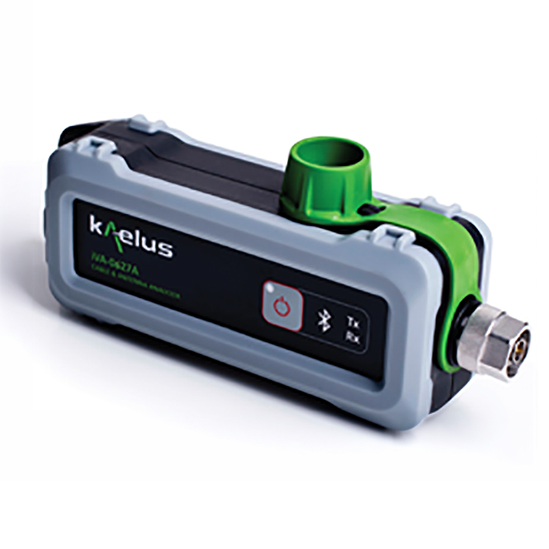
CABLE AND ANTENNA ANALYZER WITH CHANNEL POWER ANALYSIS MODE
The iVA-CPA is a new solution that adds Channel Power measurement capability to the existing base iVA analyzer. The iVA-CPA comes with all the features of the base iVA analyzer and includes Channel Power mode for additional functionality.
Channel Power mode enables the user to determine the total RF power between any two frequencies in a spectrum monitor trace. Measurement modes include CW signal and modulated signal.
FEATURES
- Measurement bandwidths of up to 75 MHz allowed
- Levels ranging from -100 to +15 dBm
- Both modulated and continuous wave signals supported
- Comes with all features of base iVA Cable and Antenna Analyzer
PRODUCT RESOURCES |
VA-CPA TECHNICAL SPECIFICATIONS |
| IVA ANALYSIS MODE – CHANNEL POWER MODE | |||||||||||||||
| Measurement modes | CW Signal Mode Modulated Signal Mode |
||||||||||||||
| Dyanamic range in CW mode | |||||||||||||||
| Low power range | -100 to -35 dBm | ||||||||||||||
| High power range | -45 to +15dBm | ||||||||||||||
| Minimum detectable signal in modulated mode | |||||||||||||||
| Low power range | 10 log(B) -87 dBm | ||||||||||||||
| High power range | 10 log(B) -32 dBm | ||||||||||||||
| Maximum detectable signal in modulated mode | |||||||||||||||
| Low power range | Min(-0.5, 10 log(B) – 14) dBm | ||||||||||||||
| High power range | +15 dBm | ||||||||||||||
| Power measurement accuracy | ± 1.5 dB typ ± 3 dB max |
||||||||||||||
| Measurement channel bandwidth | |||||||||||||||
| CW mode | 1 kHz to 20 MHz | ||||||||||||||
| Modulated mode | 1 kHz to 2190 MHz | ||||||||||||||
| Max number of measurement channels | 1 | ||||||||||||||
| Sweep speed | 2ms per frequency point | ||||||||||||||
| Maximum input power without damage | +23 dBm | ||||||||||||||
| 1 Occupied bandwidth and Adjacent Channel Power Ratio features to be included in future release of application software. 2 B is the occupied bandwidth of the measured signal in MHz. 3 Accuracy specification assumes that the measured signal is the only signal present during a measurement. The iVA’s accuracy may be degraded if other signals are present during a Channel Power measurement, especially if the aggregate RF power at the test port exceeds the iVA’s compression point. 4 Future releases of Unify will allow the user to define up to 10 simultaneous measurement channels across the frequency range of interest. |
BASE IVA TECHNICAL SPECIFICATIONS |
| KEY SPECIFICATION – IVA (SEE IVA DATASHEET FOR FULL SPECIFICATIONS) | |||||||||||||||
| iVA analysis modes | Return Loss, VSWR, Cable Loss, Distance to Fault (DTF), Isolation, Spectrum Monitor | ||||||||||||||
| Minimum frequency increment | 1kHz all modes | ||||||||||||||
| Number of measurement points | 1 to 2191 | ||||||||||||||
ELECTRICAL |
|||||||||||||||
| DC power consumption | |||||||||||||||
| Return loss mode | 4.7W | ||||||||||||||
| Transmission mode | 4.7W | ||||||||||||||
| Spectrum monitor mode | 3.7W | ||||||||||||||
| Standby (Idle) | 0.6W | ||||||||||||||
| Battery | Lithium-Ion 3.6V, 2350 mAh, 8.5Wh | ||||||||||||||
| Battery charging method | USB-compatible power source connected to USB port of iVA | ||||||||||||||
| Battery operating time | 8 Hours at typical usage factor | ||||||||||||||
INSTRUMENT CONTROL |
|||||||||||||||
| User interface | USB or Bluetooth supported user device with iVA application software installed | ||||||||||||||
| Supported devices | iPA Portable PIM Analyzer Tablet computer (iOS & Android) Smartphone (iOS & Android) PC, Windows 7,8 & 10 running .NET verson 4 or later |
||||||||||||||
| Communications interface to iVA | Bluetooth and USB 2.0 | ||||||||||||||
| Bluetooth antenna | Integrated into housing | ||||||||||||||
| Maximum input power on RF port | +23dBm maximum, DC voltage ±30V | ||||||||||||||
TECHNICAL SPECIFICATIONS |
| MECHANICAL | |||||||||||||||
| Dimensions H x D x W | 52 x 69.5 x 216mm | 2.06 x 2.73 x 8.51in | ||||||||||||||
| Weight | 0.68kg | 1.5 lbs | ||||||||||||||
| Connector 1 | RF test port iVA-0627A: Type N male, 50 ohms iVA-0627B: 4.3-10 male, 50 ohms |
||||||||||||||
| Connector 2 | USB 2.0 Mini-B (for charging and connection to iPA or PC) | ||||||||||||||
| Mechanical Shock & Vibration | MIL-PRF-28800F Class 2, ETS 300 019-2-1, -2, -7 | ||||||||||||||
ENVIRONMENTAL |
|||||||||||||||
| Temperature range | -10°C to +55°C | +14°F to +131°F (operational) | ||||||||||||||
| Ingress protection | IP54 | ||||||||||||||
| Altitude | 4600m | 15,000ft maximum | ||||||||||||||
| Compliance | EMC- EN 61326-1:2013, EN 61326-2-1:2013, EN 55022:2010 “Class A” EN 61000-4-2, 4-3, 4-4, 4-5, 4-6, 4-11 Safety- EN 61010-1:2012, EN 61010-030:2012 |
||||||||||||||
| Operational humidity | 5% to 95% RH non-condensing | ||||||||||||||
| Storage temperature range | -20°C to +60°C | -4°F to +140°F | ||||||||||||||
ORDERING INFORMATION |
| 1. CHOOSE BASE IVA WITH DESIRED ACCESSORIES |
| PART NUMBER | DESCRIPTION | ||||||||||||||
| iVA-0627A-NC | iVA Cable & Antenna Analyzer System, Type N male connector with Neoprene Soft Case | ||||||||||||||
| iVA-0627A-HC | iVA Cable and Antenna Analyzer System, Type N male connector with Hard Case | ||||||||||||||
| iVA-0627A-BK | iVA Cable & Antenna Analyzer System,Type N male connector with Basic Accessory Kit | ||||||||||||||
| iVA-0627A-SK-02 | iVA Cable & Antenna Analyzer System, Type N male connector with Standard Accessory Kit | ||||||||||||||
| iVA-0627A-PK-02 | iVA Cable & Antenna Analyzer System, Type N male connector with Premium Accessory Kit | ||||||||||||||
| 2. ADD IVA CHANNEL POWER MODE |
| PART NUMBER | DESCRIPTION | ||||||||||||||
| iVA-SW-CPA | Base iVA + Channel Power Mode | ||||||||||||||
| Contact Kaelus at 1.303.768.8080 or +1.800.498.1352 to obtain addtional information, request a quote or receive unit pricing on the Kaelus iVA – CPA analyzers. |